Where to buy
Need advice? Our highly trained dealers are happy to help with questions, small or large.
Find a dealer near you
Technical articles

Justin Tyers • 15 October 2026
Webinar Invitation: Putting Surplus Solar to Work
Join us on November 6th at 14:00 CET for the second joint webinar hosted by Shelly and Victron Energy to get a deeper understanding of smarter energy management. In the previous Shelly/Victron webinar we learned about energy measurement, surplus solar, and self-consumption. Episode Two builds on that to explore how Victron Energy data can be used to drive coordinated actions across Shelly control, sensing, visualisation, and protection solutions. Webinar hosts Lucian Popescu (Victron Energy) and Orlin Dimitrov (Shelly) will demonstrate how the two ecosystems work together to manage and prioritise GX Opportunity Loads while maintaining manual control and safe fallback behaviour. Discussion Programme The programme includes: Introduction to the Shelly and Victron Energy teams New Victron Venus OS v3.80 and GX capabilities, and support for more Shelly products Bluetooth improvements: using Shelly devices as a bluetooth range extender Opportunity Loads control with Victron Energy, Shelly, and other products Visualization and local control with Shelly Wall Display XL Circuit-level and environmental use cases with Shelly Pro CB and Shelly Weather Station Live demonstration Live Q&A What you will learn During the presentation you will learn: How Victron GX information can trigger Shelly devices; How to use Shelly devices as a bluetooth range extender; How different Shelly products support control, sensing, visualisation, and protection within an energy-management system; How to control and prioritize GX Opportunity Loads while preserving manual control and safe fallback behaviour; How the demonstrated Victron and Shelly system is structured, and How the partnership creates practical value for installers and customers. Who is it for? This information will be invaluable to PV installers using Victron devices, programmers, Electricians, Energy Consultants, Industry Professionals and DIYers interested in load automation. Registration You can register for the event right now. If you are unable to join us on the day, register anyway , and we’ll send you the recording so you can catch up later. Presenters: Lucian Popescu – Victron Energy Guy Stewart – Victron Energy Orlin Dimitrov – Shelly Shenay Okan – Shelly Privacy information This event will be recorded and shared publicly with Shelly/Victron customers, partners, employees and service providers. The recording may include your name and any questions you submit to Q&A session. By registering for the event you agree to the Privacy Policy. We look forward to seeing you!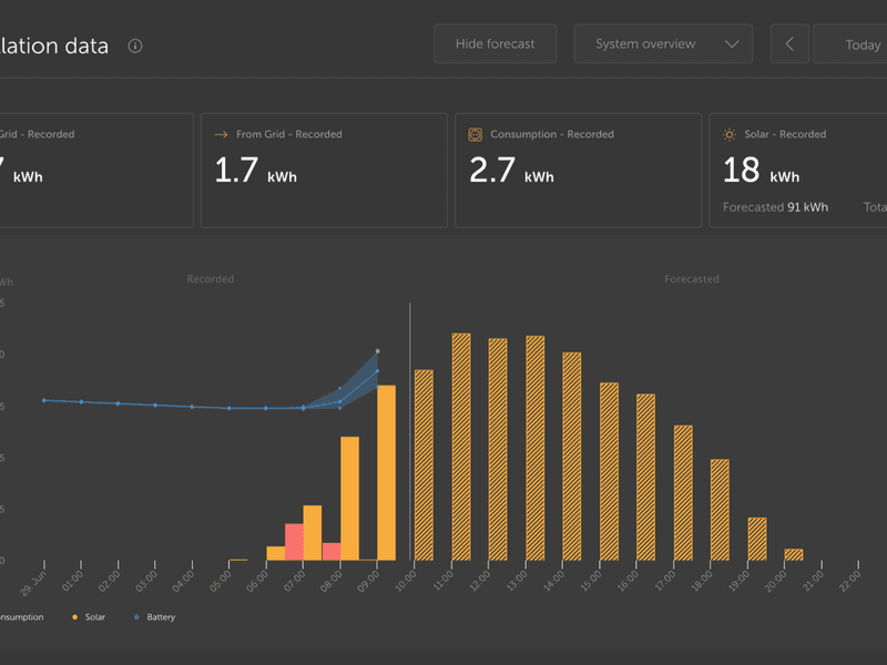
• 05 July 2023
Introducing Solar Production Forecast
We are excited to announce the launch of a new feature for VRM – Solar Forecasts. This feature combines a model of your sites solar production potential with irradiance forecasting data from Solcasts global fleet of weather satellites. https://www.victronenergy.com/blog/wp-content/uploads/sites/10/2023/07/solcast_232349675.mp4 The Solcast network provides 600 million new irradiance forecasts every hour. Getting started Existing installations with a solar history and location set can get started right now. To see the solar forecast, open your site VRM dashboard and select ‘Today’. This should reveal a Show/Hide forecast button. Clicking the Show Forecast button will expand the view to show what remains of the current day, and also draws bars to show the estimated solar production. If the forecast button isn’t there, please check: Your installation has a location set Your site is recording hourly solar yield You are on the ‘today’ view For new sites that don’t yet have a solar yield history, or if you’ve only recently set the site location, please wait up to 48 hours for it be enabled and have enough information to be accurate. This feature uses location data as a 4 km² grid, and doesn’t link any personally identifiable information or co-ordinates of your Victron site. This is accurate enough for the solar data while still maintaining your location privacy. Showing the forecast adds more information to the Solar info box on the dashboard as well. “Solar – Recorded” shows the actual solar energy that has been converted from the sun today. “Forecasted” is the estimate for how much solar production still remains for the day. This number will count down as the day progresses and the actual yield is added to the “recorded” figure. “Total” is a forecasted combined value of the forecast estimate and the actual recorded energy. There might be some rounding of these figures. How is it done? We have created a machine learning model that compares historical solar production and the irradiance at the time of day and then calculates the future projected solar production based on the estimated irradiance forecast. This automatically takes into account factors like system sizing, panel orientation & pitch, efficiency degradation, and shading without requiring any user input. This means that over time the model will get more accurate, even as panels degrade and trees grow. The model goes even further, accounting for when MPPT trackers were at maximum production, or limiting themselves (for example when batteries are full in an off-grid system). In addition to the dashboard estimate, we also have the underlying Solar Irradiance Forecast (W/m²) available as a new advanced VRM widget. Like the dashboard, in the ‘Today’ time frame view, this widget operates slightly differently to the rest and will expand out its time x-axis to include the whole 24 hours so you can see the estimate for that day. A future update for additional advanced VRM widgets will show the estimated production for each individual MPPT tracker. More functionality planned Testing is already well underway for how this new functionality can extended further, such as longer range forecasts and improving the performance of Victron systems in other ways. For example as part of a ‘ Dynamic ESS ‘ system that can take energy pricing information, combined with expectations of solar yield and decide whether to discharge or recharge the battery. It is currently not possible to see the estimates in the VRM phone app widgets. We are working on this for a later release. We’ll make another announcement with more details about these in the future. Going further with Node-RED controls For those who are interested in pushing further with this new solar yield estimate data from VRM for themselves, there is the possibility to integrate with Node-RED. For example the system could be programmed to trigger a relay control for a high load appliance based on the expectation of sufficient solar yield later that day to recharge the battery. Documentation on how to get started using data from VRM in your Node-RED flows is here . Once up and running there is even more detailed specific Node-RED estimated yield flow documentation here. As always with leading edge development like Node-RED the best place to find out more is via the Modifications space on Victron Community . Limitations Sites with these RS products may show less accurate estimates if there are other sources of solar production, or no forecast at all if they are the only source of solar production. We are working now to add full support for them in the near future. Feedback Please report any issues with the user interface, either suggestions for improvement or bugs. We are still improving the estimation algorithm, so are interested in reports of any unusual or impossible estimates. We hope you enjoy this new feature, and are looking forward to hearing your feedback .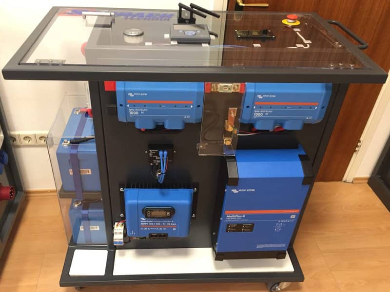
Justin Tyers • 23 March 2021
Teaching Renewables in Croatia
Right across central Europe Schrack Technik provide energy solutions to industry, home and the Electric Vehicle market. They educate customers about the advantages of Solar – and also provide demonstration mobile energy installations for the classroom. In this article Josip Zdenković (PH.D / M.Sc. E.E.) manager of Schrack Technik , Zagreb, Croatia – tells us what his team is doing to help young people in schools in his region. The idea is to use Schrack employee Dario Jankovic’s M.Sc dissertation to serve as an education for those who follow. Josip says: “We are all aware of so called Zero-Energy Buildings through concepts like Passive Houses, Green Building, or Solar Gain. Heat that is not lost does not have to be replaced. This is the key principle of the Passive House Standard and is achieved mostly by means of a well-insulated building envelope, sun shining through the windows, and a ventilation system in which heat from sources such as people and appliances is recovered from the extracted air. The reduced energy demand can be met using renewable energy sources. With regard to the remaining electrical energy requirement, we must control our mains consumption! Photovoltaics and battery storage technology enable that. “Presenting information about electronics and their features is not such a simple task – even to experienced and educated customers! So how do we present it to students aged 15 to 20, pre-university or college? “We are certain that this is the latest age at which we can inspire young people to take an interest in the field of renewables. Shall we use the component-to-system or system-to-component approach (bottom upwards or top-down) to lecturing? We decided with students to adopt a top-down strategy. “Schrack Technik uses a Victron Energy Storage System as the right story for that approach! Here is the Schrack Technik “top-down” story: “It’s clear to every student that the best houses can produce its own needs in addition to producing surplus energy for our electrical cars too! Having a good building envelope; upgrading the windows, installing a heat recovery system, what else can we do? “Today we are using mains electricity as our only energy source. The sun’s energy is at our disposal as a cost-free alternative energy source, but let’s do more. Let’s make it the dominant energy source, keeping mains energy in reserve. How much domestic energy consumption could be provided by the sun is related to power-system dimensioning. Pictured below is the whole system. The house owner should set mains house consumption. Then the actual consumption from the mains is measured. Based on difference between set and actual consumption the consumption controller will pass energy (either direct from sun, or stored from battery) to house loads. So long as there is enough energy from sun, or stored in the battery, house consumption from the mains will be hold on set point. Once there is no sun or there is no more energy stored in battery, the house will be supplied from mains as normal. “Do you think this is enough simple story for students? What are the possible ways of converting solar energy into electricity, and how to control energy flow “In order to achieve the house consumption to stay on set-point, students must understand devices and possible energy flows within those devices. In the picture below both the devices and the possible energy flows are shown. Here we will not go into detail, anyone who is reading this blog is familiar with those devices and their basic operation. Of course for students there should be added some extra words! Educational Energy Storage System based on Victron ESS “For the first set-up Schrack Technik decided to prepare minimal configuration based on Victron ESS which demonstrate the power electronic components, energy flows, and overall strategy to control house consumption from the mains. For the sake of simplicity it was decided not to use a grid inverter for the first model set up, but it can be employed at anytime – the model housing is managed in this way too. Also single phase ESS has been chosen instead of three phase ESS. For educational purposes, single phase ESS is sufficient to show strategy of house mains consumption control! Model set up “Schrack Technik model set up is designed to be mobile. That simply means it is on wheels so that the model can be taken from classroom to classroom. Each classroom should have a 5 pole mains outlet (L1,L2,L3,N,PE – full TN-C-S connection) to connect mobile set up to the mains electricity. “This model emulates a typical house load and typical connections. Loads could be connected to all phases and to MultiPlus II output. This set up can demonstrate off-grid systems too. Photovoltaic modules can be connected to the system, or alternatively a power supply (voltage source with current limitation) can be used. This is important because during the lecture it may be cloudy and the PV modules may not be producing electricity. Devices hang on all three sides of the housing, the fourth side is reserved for grid inverter option. Battery monitor , Color control and Digital Multi Control are installed on a glass top – allowing a view to the back side wiring. Electrical set up schemes “The next two schematics show set-up detail: power components and communication components. Atypically, it is the Battery Monitor and the Color Control connection. Supply of these devices is connected after main battery switch …so when the Lithium batteries are switched off no current is drained from them. This is for safety reasons: because the models are mobile they will not permanently be connected to the mains. When not in use the LFP battery should be switched off from any load. What’s inside?: – Multiplus II 24/3000 – SmartSolar MPPT 150/100 VE.Can – Color Control GX – Energy meter EM 24 – 2 x LiFePO4 Batteries 12,8 V/100 Ah smart – VE.Bus BMS – BMV 712 Smart – 2 Lynx Power in – Digital Multi Control – together with all necessary fuses, switches, protections, cables and covers Donation “Schrack Technik d.o.o. donated a mobile ESS for education to three schools in 2020. There will be three more beneficiaries in 2021. We connect all the teachers involved, so they can exchange experience, working materials and ideas for practical exercises. Schrack Technik trained the teachers – now it is their turn to promote house consumption control to their students. All teachers get administrator access on their installations on the Victron Remote Management (VRM) portal – which allows remote system control and monitoring. Schrack Technik believes that a lot of students will absorb the idea of mains house consumption control. They will learn how simply it can be commissioned and followed on VRM portal and how useful is to control house consumption from mains. Playing with such simple system will enocurage young future installers – freeing of any hesitation about PV installation! High school Konjščina has 270 students and an electrical engineering department. Course tutors Ivana Smetiško, Dalibor Smetiško, Mario Varga, Milan Havoić invest their own time making sure their students have access to the latest developments. Building a Schrack electrical laboratory – they hope to become a centre of competence in renewables education. Electro-mechanical vocational school, Selska , has 600 students. Three enthusiastic teachers: Damir Čolig, Ratko Harausek and Mladen Klobučar lecture in renewables. With a focus on mechanical and electrical engineering they demonstrate the application of the science around real-world examples such as motor vehicles. Technical school, Daruvar, has 474 students whose education is focused on trades and technology. Mario Havranek is the lecturer in renewables, and has a particular interest in Zero-Energy building. He is pleased to be able to offer his students training using the very latest technical equipment. “All students get a copy of the 400 page Schrack Technik brochure showing photovoltaic technology using Victron products, in the main, together with practical examples of Solar installations. Schrack have given away 3000 copies since the programme began 5 years ago.” And for those who speak Croatian and are keen to learn more about the practical application of Victron products – here is a video lecture which has been put together for students of renewables:
Justin Tyers • 30 October 2020
How to Install a MultiPlus Inverter/Charger?
Peter Kennedy is an experienced Victron Dealer/Installer specialising in Marine applications. His company website PKYS carries a useful guide to installing a MultiPlus Inverter. In it Peter adds a whole world of information to the Victron Energy MultiPlus installation manual. He discusses the practicalities of installing a MultiPlus Inverter in compliance with the standards of the American Boat and Yacht Council ( ABYC ); he explains what we’re looking at when we remove the front panel; and he explains the connection-options to other devices. We are grateful to him for allowing us to reproduce his advice here: Introduction This article details the installation of the US Version of the Multiplus 12/3000. This is a 12 Volt DC 120 Volt AC inverter/charger. The official title is MultiPlus 12/3000/120-50 120V VE.Bus and the title indicates that the inverter output is 3000 VA, the charger is rated for 120 Amps and it has a 50 Amp transfer switch. This blog post details unpacking, mounting and wiring your new MultiPlus. Quick Install Sheet If you have built an Ikea bookcase you will instantly recognize the style of the Quick Install Sheet . It is showing you what is in the box, what isn’t in the box, how to mount the unit and how to wire it up. It’s not that easy to follow, so I am going to interpret it in conjunction with the other more detailed manuals, which lack drawings, and I will maybe throw in a photo or two for good measure. What’s included in the box? Multi Plus Wall mounting plate Fasteners Temperature sensor, User manuals What’s not included? Battery Battery cable Battery switch Fuse and fuseholder Remote control panel Cable to connect remote control panel AC input wires AC output wires Grounding cable Voltage sense cable Other optional cables Don’t install an inverter above the batteries This is an ABYC requirement. Lead acid batteries give off corrosive gases that can destroy equipment directly above them, even sealed batteries can vent corrosive gases on occasion. The following diagram is showing you that the MultiPlus needs some space around it for ventilation. The Service Manual gives you more details about the mounting including the following: “The product must be installed in a dry and well-ventilated area, as close as possible to the batteries. There should be a clear space of at least 10cm around the appliance for cooling.”; and also: “The device can be fitted either horizontally or vertically . For optimal cooling, vertical fitting is preferred .” There is more mounting information in the Service manual. Mounting is easy You screw the mounting bracket to the wall. Hang the MultiPlus on the bracket. Pop two screws in the bottom to stop it jumping off. If you are installing it horizontally the same applies. Connecting the small cables This next diagram is a bit confusing because the current model of the MultiPlus doesn’t look like the drawing. At this point it would be helpful to have an actual photograph to see what it really looks like. As we go along I will explain what all the connections are. In the service manual Appendix A gives a drawing to help identify the components and connections. Here’s a photograph of the same view: The connections for the small wires are all in the set of green terminals in the very bottom of the photo. They are all labelled as E in the diagram above. The image below shows what they look like without the wires in the way: The first pair labelled T-Sense are for a temperature sensor. The sensor mounts on the battery negative terminal. The wires are labelled +ive for red and -ive for black. The Aux1 and Aux2 are input terminals and are programmable. We will discuss these when we get to the programming section in a future blog post, typical uses include remote control from the Battery Management System (BMS) of a Lithium Battery where they could be programmed as “allow to charge” and “allow to discharge” The Ground Relay terminal is used if you are installing an Autotransformer, see Autotransformer Instructions for further details The trickle charger terminal can be used for charging an auxiliary battery such as a starting battery. This is just the positive connection. The battery negatives must be common to each other. Max output is 4 Amps K1 and K2 terminals are relay contacts which are programmable and can be used, for example, to automatically start a generator The V Sense wire can be connected to the battery to give a more accurate reading of the battery avoiding voltage drop in the battery main cables. Installing a voltage sense wire is not required but it does give improved performance because the sensor reads the actual battery voltage and can compensate when charging for up to a one volt drop in the cables. There is a +ive and -ive connection that goes to battery positive and negative. (A fuse is required) Main Battery Cables The next panel shows the main battery cable connections. In the diagram above they show a single positive and a single negative cable, but if you look at the picture below you can see there are two studs you can connect to for each with the intention that if necessary you can double-up the cables. The diagram above does not show a battery switch but in the ABYC standards this is a requirement. You need to be able to turn this off if there is a problem or if you want to work on the system. The service manual goes into the cable size in some detail. The service manual suggests using doubled-up 1/0 cables for the main supply and suggests using a 400 Amp fuse for the 12/3000 multiplus. A Class T fuse would be appropriate for this application. The ABYC has quite a bit to say about using doubled-up connectors like this; I have summarized it in the footnotes. According to my reading of the ABYC standard if you were using standard 105°C rated battery cable you would need to use 4/0 AWG cable if you had a 400 amp fuse in the line. The main principal to bear in mind here is that the cables carry a lot of load and the load carrying capacity must match the circuit protection. If doubled-up cables are used the ABYC says each individual cable must be capable of carrying the entire load by itself and they must share a single fuse. The cables need to be as short as possible to reduce voltage drop, the longer they are the greater the cross sectional area needs to be, and the less voltage drop there is the better the performance. Aux Battery Charger This next panel shows the charging circuit for an auxiliary battery such as a starting battery. It has a maximum 4 amp output. The drawing shows that the Aux battery and the Main battery must share a common negative. Then the only wire you need for this is the positive wire. The drawing doesn’t show a fuse for this wire but one is required at the battery end. The wire connects to the terminal labelled “trickle charge” in the middle of the set of green terminal strips. Connecting a remote panel A remote panel is not included with the MultiPlus but is available separately. There are two versions, the Digital Multi Control and the Digital Multi Control GX . These are functionally identical but have a slightly different appearance, the GX version is designed to match the appearance of the Color Control GX . The port is called a VE Bus port and the cable needed for this is the RJ45 UTP cable – also sold separately. It plugs into the position labelled “B” in the big drawing above (titled ‘Appendix A’) and in the photo at the end of this article. There are two adjacent sockets and you can plug it into either, they are identical. There are other things you can plug in there too including a parallel cable to connect multiple units or the new VE.Bus Bluetooth Dongle. Here is a photo showing two devices plugged in. AC Case ground There is a terminal for connecting an AC Case Ground. I wasn’t able to find any written reference to this in either of the other manuals. The ABYC does have some things to say about case grounds for Inverter/Chargers though. AC Output Connections The MultiPlus 12/3000 has dual AC Outputs. AC Output 1 is the main output. It supplies power regardless of whether shore or generator power is available or not and is the output on which the ‘PowerAssist’ feature is available. PowerAssist adds battery power to an AC source (shore or generator for example) when the on-board power demand would otherwise exceed the available current limit. AC Output 2 is only live when the MultiPlus is connected to an external AC source (eg. shore or generator). The thinking here is that by using AC Output 2 for non essential loads like water heaters, you’ll never accidentally drain the batteries if the generator or shore power fails. Each output has terminals for Line, Neutral and Ground. The Ground output is shared between the two outputs. Here is a photo: AC Output 2 is limited to 32 Amps. The Service manual details the recommended wire sizes based on a 50 Amp shore or generator input, see below. The output wires are sized to add the inverter’s PowerAssist amps to the shore or generator power available. For configurations with less than 50 Amp shore-power/generator power or installations where PowerAssist is disabled it should be possible to reduce the necessary wire size by reference to the ABYC tables. AC Input Connections The AC input terminals are on the extreme left and comprise a Line, Neutral and Ground terminal. Recommendations for wire size are shown in the table above and are based on a 50 Amp shore or generator supply. Finishing the Installation Before you put the panel back on you may want to check your work. Have you got the polarity right for the DC terminals? Reverse polarity on these is a fatal error that will destroy the unit. Are the bolts tight? Have you mixed up your incoming and outgoing AC connections? Are those screws tight? Have you connected all the optional extra devices? There are also a few things you might like to look at before you close the lid so I have annotated the photo below with some notes. For most installations you will want to at least do some basic programming of this device. The most basic programming is done using the dipswitches and that requires the cover to be open. Anything more elaborate should be done using one of the computer interfaces available, such as VE Configure . You might also like to make a note of the model and serial number, and the processor number as these are all things you might need later and it’s a lot easier to write them down in the manual than it is to go and open up the unit again. In the photo below I used the same letter key as in the drawing earlier in the article. Below the photo is a list of what all these items are. A AC Input connections B VE.Bus ports for remote panel, parallel configurations etc. (Both ports are identical – you can use either or both.) C AC Output 1 – this is the primary output D AC Output 2 – only works on shore power or generator and is limited to 32 Amps E Optional ports for temp sensor, voltage sensor, programmable options F DC negative connection (dual terminals available if double cables are used) G DC positive connection (dual terminals available) H Connector for remote switch (On, Off, Charger only) I Programmable relay alarm contact. K On-Off Push buttons used in conjunction with dipswitches for basic programming M Dipswitches used for basic programming N Slide switches. Slide switch 1 is used for the ground relay function if the unit is connected to an autotransformer. Switch 2 is not currently used for anything. X Main Processor, make a note of the number in case a firmware update is ever needed (hint: take a photo) The first four digits of the processor number must match the first four digits of the firmware file name. Y Serial number and model number, make a note or take a photo. All the above is taken from Appendix A of the service manual which has additional information on the functions of each item. Other versions of this MultiPlus The 24 volt version of this should be almost identical (24/3000) The “ Compact ” 12/2000 MultiPlus is a bit different, it only has a single AC output and it has a greatly reduced number of terminals for optional connections. Quattros These photos are of a 48 Volt 5000 VA Quattro . You can click on the thumbnail to enlarge the photos. The first one is the AC wiring area and the second is the DC wiring area and all the small connection points. User manuals The following manuals are available for the MultiPlus, I’m not sure which ones are in the box: Quick Install Sheet . User Manual Service Manual . Next steps Programming the MultiPlus is detailed in subsequent articles starting with this one about programming the MultiPlus using the dipswitches . ABYC NOTES From E-11 AC & DC ELECTRICAL SYSTEMS ON BOATS ABYC 11.6.1.2.1 A battery switch shall be installed in the positive conductor(s) from each battery or battery bank with a CCA rating greater than 800 amperes or 100 Ah if CCA is unavailable. 11.10.1.4 Non-motor Loads – The current rating of the overcurrent protection device shall not exceed the maximum current-carrying capacity of the conductor being protected (see TABLES 6A-B). EXCEPTION: If there is not a standard current rating of the overcurrent protection device equal to 100% of the allowable current for the conductor in TABLES 6A-B, the next larger standard current rating may be used, provided it does not exceed 150% of the current allowed by TABLES 6A-B. 11.14.1.2.8 Paralleling of Conductors – conductors of #10 AWG and larger shall be permitted to be connected in parallel where the ampacity of each individual conductor is sufficient to carry the entire load current shared by the parallel conductors. NOTE: Paralleled conductors may be used to achieve the appropriate voltage drop or wire bend radius with smaller individual cables. 11.14.1.2.8.1 Overcurrent protection of paralleled conductors shall be sized to protect a single conductor. 11.14.1.2.8.2 Paralleled conductors shall be of the same length and gauge. 11.14.1.2.8.3 Paralleled conductors shall be run together in the same cable, bundle, or raceway. Here is a link to the Ampacity Tables referred to above, in almost all cases we are using battery cable with 105°C insulation. According to the ABYC if you put a 400 amp fuse in the line then you have to use 4/0 cable. Two times 2/0, which has the same cross sectional area, doesn’t comply because the individual cable is not capable of carrying 400 Amps. I called them up at the ABYC to get some clarification on circuit protection for doubled-up cables. You can use either one fuse or two if you have double cables, but in either case the fuse needs to be sized for what a single cable can carry. From A-31 BATTERY CHARGERS AND INVERTERS MOUNTING 31.5.5.6 To avoid corrosive fumes, battery chargers, inverters and inverter/chargers shall not be installed directly over batteries. 31.6.5 DC GROUNDING CONNECTIONS 31.6.5.1 The DC grounding conductor shall, 31.6.5.1.1 be connected from the metallic case or chassis, to the engine negative terminal or its bus, and 31.6.5.1.2 shall be of an ampacity equal to that of the DC positive conductor. EXCEPTION: The DC grounding conductor may be one size smaller than the minimum size conductor required for the DC current carrying conductors.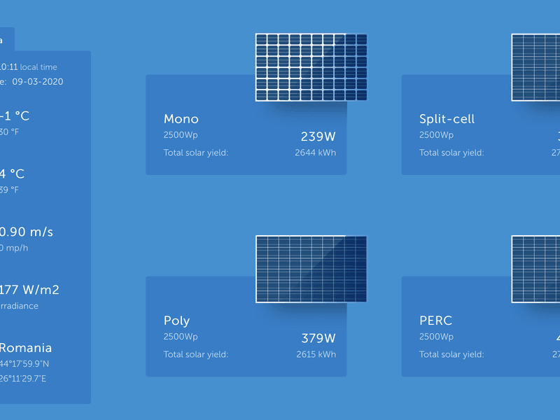
Justin Tyers • 12 October 2020
Which Solar Panel?
Ever wondered which type of PV panel offers the best output? We wondered that too! So we decided to carry out our own impartial test. Don’t worry, we’re not setting out to prove that Victron Panels are best or anything like that. We thought it would be interesting to compare Monocrystalline cells with Polycrystalline; Passivated Emitter and Rear Cell ( PERC ) panels; and ‘Split-Cell’ panels – which are wired to reduce hot spots and increase efficiency. So we installed those four types of array, outdoors, making sure the installations were identical in every way: they’re in the same location (obviously!) they have the same length of cabling; they’re connected to identical MPPT solar chargers panel output is mathematically re-calculated to show results as if each array had a 2500Wp The test has been running for six months and will continue indefinitely. You can view the live data, and see the total power harvest which has accumulated over time. By way of an example here’s a snap-shot comparison for one moment in time: When the monos were producing 1430 Watts, this was the live comparison: Monocrystalline = 1430W Polycrystalline = 1366W PERC = 1427W Split Cell = 1439 What makes the experiment interesting is that different panels offer their best performance under different weather conditions. Local ‘live’ meteorological conditions are reported alongside the panel readings. At the time of writing, in the Northern Hemisphere, we are coming into our winter. Clear cold winter days of brilliant sunshine are great for harvesting solar energy – so let’s see what happens! To see live data from our test go to the Victron Energy homepage and click on Field Test – which you’ll find top left of screen, on the site-map black-strip. (Field Test cannot yet be viewed on mobile phones.) Take a look at this video to see how our 4 panel arrays were set up for comparison-testing, and how the results can be compared.
Justin Tyers • 20 February 2020
PV Panel output voltage – shadow effect?
So much can be learned from the discussions taking place right now on the Victron Community pages. Subscription is free of course, and you are very welcome to join in. With credit to John, M Lange and Guy Stewart we thought we would highlight a recent discussion which shines a light onto Photovoltaic panels, and what happens to their voltage and current output in conditions of shade. Here’s what we learned: Solar panels, unless heavily shaded have a remarkably high and consistent voltage output even as the intensity of the sun changes. It is predominantly the current output that decreases as light intensity falls. Panel temperature will affect voltage – as has been discussed in another blog . Have a look at these I-V (Current vs Voltage) and P-V (Power vs Voltage) charts for a 305W solar panel from Trina Solar . You can see in the P-V curve that as the solar radiation decreases from 1000W/m2 to 200W/m2, the power drops proportionally – from 300W to 60W. The Voltage output range remains nearly constant, however with the Maximum Power Point (MPP) voltage at 33V, and the maximum open circuit voltage only dropping from 43V to 38V. If the voltage is pretty constant regardless of the intensity of the light, then the Current must be changing. (Note that these tests were all run at 25°C) You can see this clearly in the I-V curve, where the output current has dropped from 9.8 A at 1000W/m2 to 2 A at 200W/m2. Clear skies What this means is that the input voltage in a correctly designed and installed system, with a clear view of the sky, should nearly always be within the acceptable voltage window of the MPPT for optimum performance (even when its cloudy). Heavy shading from a tree for example – or when panels become extremely hot – DOES affect voltage markedly. Due to the nature of the semi-conductive silicon in PV cells, the effect of a blocking shade on the solar panel is so severe that if a single cell (of which there can be between 36 and 144 in each panel) is completely shaded, it will completely restrict the flow of electricity through it. Solar panels have built-in bypass diodes to skip a troublesome cell group (usually several horizontal columns of cells) allowing the energy from the other unshaded cells to flow once more. Take a look at GIFs below displaying information from a Victron MPPT – as seen on an iPhone via the free-to-use app VictronConnect – and you will see the relationship between Solar Voltage, and the Battery Voltage. These images are dynamic when clicked: Now here is the same solar array a short time later when the sun has come out. Notice how the power has increased from ~350W to ~1000W, but the PV Solar Voltage is the same! The Victron MPPT is a buck DC to DC converter. It reduces the higher PV side voltage to the lower Battery side voltage. It can’t boost the (too low) voltage from a PV panel in order to begin charging a battery. Working at up to 98% efficiency the MPPT can accept any PV side voltage up to its maximum PV input voltage limit. This varies with the Victron models between 75V and 250V and is clearly printed on the unit itself, and all associated documentation. On the battery side, it is the battery which sets the system voltage. The MPPT takes the panel voltage and converts it to a charging voltage which is higher than battery voltage in order to get current to flow into the battery , the voltage is reduced, the current goes up, and the power remains the same . But the battery chemistry will be dragging that MPPT voltage down at the DC bus level, and that electrical work is going into the battery chemistry to charge it. Once the battery is full, and reaches a target voltage, the MPPT will adjust its voltage conversion to maintain a pre-set float voltage which is still higher than the battery voltage at rest – but not high enough to provide a significant current flow …which avoids the battery becoming overcharged. Bulk, Absorption, Float… Solar charger output voltage depends on where the connected battery is in its charging cycle (bulk, absorption, float) – the voltage of each stage being pre-set by battery charging algorithm employed by the MPPT. (The target voltage for each step can also be user-defined.) In the case of a nearly empty lead battery at 11.5V the MPPT begins work by ‘Bulk’ charging with as much power as it can get from the solar panel(s) (unless a lower current-limit has been set) until it reaches the absorption voltage of 14.4V. The MPPT will only begin charging when there is sufficient solar radiation to cause the PV panel voltage to rise 5V above the Battery voltage. After that condition has been met it will continue charging as long as the PV voltage remains at least 1V higher than the Battery voltage (or until the battery is full). In the example above: The MPPT will begin charging when the panels provide around 16.5V …and will need a minimum of 12.5 V rising to 15.4V to continue charging. When planning your installation you may find it helpful to use this ready made solar charging calculator to choose suitably sized equipment. Panel Voltage consistently lower than expected? Given that we know PV voltage SHOULD stay consistently high, what can we do if we see an unexpectedly low panel-side voltage in VictronConnect, or using a voltmeter? The first thing to do would be to physically inspect the panels (if it’s safe to do so) and make sure there isn’t some obvious obstruction. Mould can build up along the bottom edge of a row of flat panels when water isn’t able to drain properly, which reduces the output of the entire array. If everything looks normal after a visual inspection, check the outdoor terminal connections – these will usually be MC4 connectors which can be separated using an inexpensive specialist tool (or without one – though with greater difficulty). It’s important to make and break these connections only when the panel is under no load – this means either covering the panel to exclude light, or working very early or very late in the day. When the MC4 connector is open it can be visually inspected and any corrosion or oxides cleaned away by spraying the male and female terminals with a Switch or Contact Cleaner. Check the indoor connections too – but not during the day. The next level of panel testing uses a thermal camera – but don’t worry, although this requires more specialised test equipment, it is available quite affordably as a mobile phone accessory. Or try calling around solar installers, or electricians. They use them to fault-find on distribution boards. As long as the panel is still connected in the circuit, any resistance to the flow of electricity will show up as heat. Close inspection can reveal damage, or delamination. The second image shows a problem where two columns of cells are hotter than those around them. A closer inspection of the cells revealed some cracking and delamination. Depending on the severity, and the cause, it could be panel warranty issue. The problem could also be on the OTHER side of the panels, where the wiring is connected. Look for anything out of the ordinary: corrosion, melting, marks, or other damage. Be extremely careful; and don’t touch anything without taking the necessary electrical and physical safety precautions. Please remember that strings of panels generate high voltages which can be dangerous, or fatal. The National Electrical Code (USA) requires all terminals carrying more than 50VDC to be covered, protecting them – well, us – against accidental contact. The code also requires individuals working on circuits carrying more than 100VDC to be trained for that work. If you have any questions, comments or advice for others on this topic – or any other topic concerning remote energy – why not register onto our community page and join in the discussion? On the Community page your technical question will be answered quickly, by knowledgeable Victron users …and occasionally staff. (Although we continue to place the DISQUS comment hosting service at the end of each blog, we do so for non-technical comments …as it is not routinely monitored by technical staff.)
John Rushworth • 07 January 2020
Raymarine & Victron integration video
It’s that time of year in the UK, when many a boat is hauled out and their owners upgrade and maintain their systems. Victron video Victron video producer Jonathan Cecil recently took a trip to Whitehaven Boatyard in Cumbria to see what such owners, Victron dealers and installers get up to over the winter period – and in so doing produced the fascinating video embedded later in this blog. Upgrade brief In this instance the brief, to Victron specialist Chris Dobson of UK Marine Electronics Ltd., was a full Victron and Raymarine upgrade for sailing yacht Pilgrim, including a lithium battery system, upgrading Victron power systems and integrating them with a new Raymarine MFD. Pilgrim prepares for her winter haul-out Pilgrim was built on the Hamble in 2002, is 32′ LOA, planking construction and sheathed in epoxy – making for a heavy displacement, stable vessel. Raymarine integration This very useful upgrade with the advent of Victron’s latest Venus OS for their GX devices and the release of Raymarine’s latest Lighthouse software, means that users can view the status of Victron equipment on their Raymarine MFD. A Venus GX is device is able to communicate with the Raymarine Axiom Multi Functional Display (MFD) either directly or through a network router, via the Ethernet port and a RayNet adapter. Upgrade components Raymarine Equipment Raymarine Axiom 12 Display with RealVisio 3D Sonar Lighthouse 3 Software Update to Firmware: v3.11.42 i60 Wind Instrument i50 Speed and Depth Instruments Quantum Wireless Chirp Radar Click image to download PDF schematic The Raymarine Equipment is connected together with NMEA 2000 / SeaTalk ng . In this installation the Victron Venus GX is connected to the Axiom MFD via Ethernet with the Raymarine RayNet Female to RJ45 Male Cable adapter. It is also possible to connect all the Victron components to a Venus GX device, and have that connect to NMEA 2000 as well, providing yet another way to display your power system information on your boat’s Multi Functional Display/s. Victron Equipment Venus GX MultiPlus Compact 12 |1600 | 70 VE.Bus BMS 2 x 150Ah Victron Lithium LiFePO4 batteries BMV-712 Smart battery monitor and shunt SmartSolar charge controller MPPT 75 | 15 BatteryProtect 65A to disconnect solar charge BatteryProtect 220A to disconnect 12v load 50A Buck-Boost DC-DC Converter for engine alternator to control the power to the Lithiums Blue Smart IP65 Battery Charger 12v 15A Click image to download PDF schematic Video – Raymarine & Victron Integration Learn more – MFD integration for Raymarine and other brands For the full documentation about MFD and NMEA 2000 integration, please see the following. The main NMEA 2000 & MFD integration guide https://www.victronenergy.com/live/ve.can:nmea-2000:start Integrating with GX Devices For MFD App-type integration: https://www.victronenergy.com/live/ccgx:start#marine_mfd_integration_by_app For NMEA 2000 integration: https://www.victronenergy.com/live/ccgx:start#marine_mfd_integration_by_nmea_2000 Lithium cold charging issue Chris Dobson (seen in the video above) loves problems and is very keen to solve them, especially ones such as – lithium don’t like to be charged below 5C. This being an issue, Chris thought outside the box and used the resistance properties of a Venus GX to measure the temperature of the battery box, which in turn controlled a relay. Chris used a PT100 temperature probe inside the battery box, between the batteries, which is a resistance probe. As the Venus GX uses resistance for its tank levels, Chris used this to control one of the Venus GX relays. This, in turn, controlled a 12v Coil VF4 SPDT relay to turn a 12V 30W heat pad on/off, that was placed under the batteries. Whilst not included in the video, Chris also insulated the battery box and added some strips of ply to form an air gap between the heat pad, aluminium sheets and the batteries – so they weren’t just sitting on the heat source. Conclusion Apart from the innovative solution for ensuring lithium batteries are charged correctly when it’s cold outside, it’s great to see how well Victron GX devices now integrate with Raymarine MFDs. A winning combination for many boat owners, I suspect. For any technical discussions regarding this blog (rather than using Disqus below) please see this thread on the Victron Community: https://community.victronenergy.com/articles/38545/raymarine-victron-integration-aboard-a-32-foot-sai.html John Rushworth Credits Installer – Chris Dobson for UK Marine Electronics Ltd., who are a Victron Dealer in Whitehaven, Cumbria and offer marine, off-grid & backup, energy storage and support. Website – https://www.ukmel.co.uk Facebook – https://www.facebook.com/UKMEL/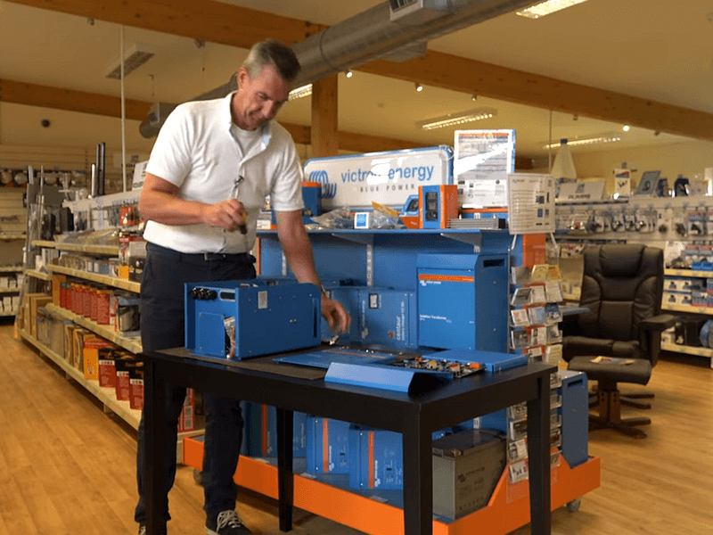
John Rushworth • 28 November 2019
Inside the Victron MultiPlus with Johannes Boonstra
It’s sometime ago since I wrote about how I used a MultiPlus on an electric sailing yacht – MultiPlus magic: Small generator, big power . I wish Johannes had done this new video back then – I might not have had to do so much reading to discover how they work! Here then is that new video with work colleague Johannes Boonstra explaining the MultiPlus and how it works. John Rushworth Credits The video producer is Jonathan Cecil . The video was filmed at Midland Chandlers in the UK, who have four well stocked showrooms based in Preston Brook (Warrington), Braunston (Daventry), Penkridge (Staffordshire) and Willington (Derbyshire). Midland Chandlers have been established for over 40 years and are a Victron Energy dealer and market leader in the supply of equipment for inland waterways craft.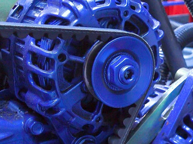
John Rushworth • 07 October 2019
Careful – Alternator Charging Lithium
Charging lithium batteries from an alternator, be that in a boat or vehicle, presents some challenges when compared to the straightforward nature of charging lead based batteries. The video in this blog highlights these lithium challenges and shows you what can happen when things go wrong – namely alternator overheating, smoke and an expensive alternator replacement, not to mention the risk of a battery thermal event. Challenges when charging lithium with an alternator The two key issues demonstrated in the video are: Alternator overheating Alternator rectifier diodes failing because of over voltage after disconnect by a BMS Test rig The test rig in the video is by Victron Energy dealer, ATI Energy, Bucharest. Lithium charging video In this video, by Jonathan Cecil of Journey with Jono, we put both a traditional and a regulated alternator through their paces. Using different RPM, we charge a 300Ah lithium battery and test the results. Conclusion It’s only by using the correct lithium battery charging solution/s in a given situation, that you can be sure of system safety. Victron have a range of solutions, such as the Buck-Boost DC-DC Converter (used in the Victron Van install ), and the similar lower power Orion-Tr Smart DC-DC Charger Isolated , as well as the BMS 12/200 as used in Jono’s canal barge, plus more on the way. BMS 12/200 installed in Jono’s canal barge. So – stay tuned, as Victron are in the middle of expanding their range of alternator charging for lithium batteries. In the meantime make sure you are using the right tool for the job – all of which can be discussed on the Victron Community . John Rushworth Links ATI Energy website ATI Energy on Facebook Journey with Jono on YouTube Journey with Jono on Facebook Journey with Jono website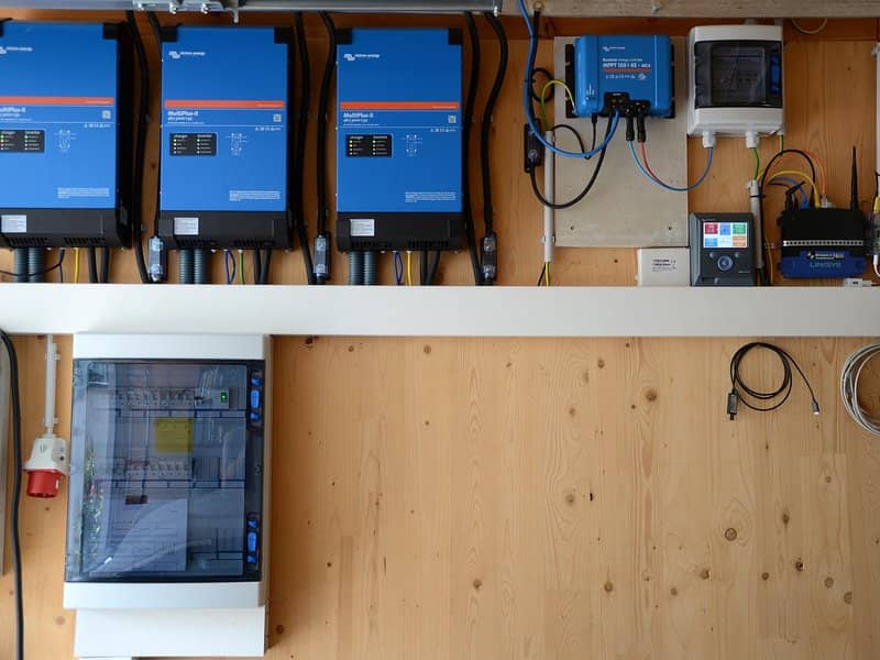
John Rushworth • 19 September 2019
Msol GmbH – A PV, Energy Storage & UPS project
It’s great to hear from Victron Energy customers, be they end users, dealers or indeed budding dealers and installers. Here’s a case in point. Bernhard Matschinger got in touch with me lauding Victron’s products, which initially led him to build his own PV, Energy Storage UPS system and ultimately his own company – Msol GmbH. For Bernhard this project was a prototype and proof of concept, as it uses non Victron Energy batteries/BMS. That being the case, this gives rise to important safety and system integration considerations. More of that later, but first a bit of history. Where it all started Back in 2013, when Bernhard saw his first ‘ mjlorton ‘ video on YouTube (228K subscribers) he became fascinated by Victron Products. Here’s an example video from that time. Bernhard is a qualified Civil Engineer with 25 years experience in designing/building low energy homes and industrial buildings. Having been the CTO of a construction company for many years he also made his IT hobby into a profession too, around 10 years ago. So now he has two strings to his bow – one in design and construction, the other creating software based on C#, .Net for Web and ERP. Due to his experience it was natural for him to want his own PV, Energy Storage & UPS system – so he built one. System background Eight years ago Bernhard and his wife built their own low energy family home from scratch, doing nearly all the work themselves. The area of their home is 255 m², which per annum requires around 2,300 kWh of electricity (6.3 kWh/day), plus 2,600 kWh (7.12kWh/day) for hot water – giving a total of 13.42 kWh/day of electrical energy needs. For space heating they use around 500 kg of wood pellets per annum. The resulting direct energy costs are around 100 € for heating per year, 260 € for hot water (5 persons) and about 320 € / year for grid energy. That equates to about 1.86 € per day for heat and electricity – significantly less than their neighbours in the region. However when the family got a Tesla Model S, energy usage increased somewhat. Tesla Model S charging With these increased energy needs and since building their home, Bernhard had always been looking for some grid independence, with ways to reduce direct energy costs, plus a route to ensure no power blackouts. Standalone PV made little sense, as in the day the family is mostly away from home when excess solar power is available, plus feeding back to the grid pays peanuts at 3.9 cents per kWh. Everything changed though when he discovered Victron products – a result of lots of YouTube research, website surfing, drawings, calculations and finally discovering the Victron MultiPlus – one of his favourite bits of kit that has just what he needs. Time for some shopping Retail therapy… The primary shopping list: 3 x MultiPlus-II 1 x BlueSolar 150/45 MPPT 1 x Color Control GX 24 x 280 Wp Solar Panels 16 x LiFeYPo4 cells 260 Ah 1 x SolarEdge 5kW + 18 Optimizer 1 x Active BMS by AutarcTech The build Every carport array needs a little solar helper… A very neat installation. Documenting the first 8 of 16 battery cells being equalised. The battery housing is made of 6 mm Promatect (a fire resistant material) which is designed for 60 min fire resistance. Mounting the Multis, cable trunking and starting to create the fire-resistant housing and rack for the battery cells. Sturdy 70mm² cables. BMS data collection – Software C#, written by Bernhard. Up and running with the Color Control GX. Safety & system integration considerations With many people now wishing to use second-life batteries (Tesla for example) or indeed new individual cells made into a self-build battery bank, as Berhnard has done – it is very important to be aware of the safety considerations when integrating Victron Energy power products with non Victron batteries and a non Victron supported BMS. Prior to publishing this blog, we wanted to be certain Bernhard had catered for key safety aspects with his choice of battery/cells – so, we asked: “Can you confirm if you have installed a safety contactor between the battery and the rest of system, and how that is switched?” Bernhard responded: “It is absolutely independent, and yes, there are all breaks on the positive side. The negative side is connected to the common negative pole and is not switchable; all fusing (also the CCGX, the MPPT and the 3 x MultiPlus-II) is done on the positive side. There is a 200A Fuse inside the Battery housing, a manual Contactor (Emergency Switch) and an automatic Relay Contact, driven by the BMS. The cabling is 70 mm² oilflex copper cabling with 3 safety layers.” “As regards the active BMS by AutarcTech, it monitors each cell for voltage and temperature; plus it monitors the whole bank for max charge and discharge current, over and under voltage and over and under temperature. It also operates the main contactor.” Bernhard also wrote his own software in Python and C# to collect data from the AutarcTech BMS, to display that data in Visu. Bernhard’s software, using Visu to display the data for his own personal interest which shows the behaviour of the cells: voltage, charging, discharging or inactive state. Note: specific information about non Victron, yet compatible batteries that have been tested and are supported can be found here . Now let’s deal with all the caveats, from a Victron viewpoint, that relate to similar systems to Bernhard’s and integration with Victron products. Victron Energy safety & liability statement Here’s what Matthijs Vader, Victron Energy MD had to say: “To make for a safe lithium system; there must be a mechanism in place that automatically disconnects the battery from the rest of the system on cell under-voltage, over voltage and also on cell-temperature issues as well as other adverse conditions. This means that the voltage on each cell needs to be measured individually. And also temperature needs to be measured and monitored; preferably at cell level, but usually it is also OK to measure it for a certain number of cells together. Those measurements must be taken care of by a BMS. At Victron we do make BMS-es, but they are only to be used with our own batteries. We do not make general purpose BMS-es. Also, the under voltage lockout of an inverter, and the over voltage protection in a battery charger can *not* substitute a BMS: both only measure total battery voltage, rather than the required individual cell voltages, and temperatures. Finally, the BMS must control a contactor, that disconnects the battery from the rest of the system. Please take this seriously, any Tesla or other cell over and under voltage can lead to explosive fires and other severe issues. For which at Victron we take zero responsibility and also accept no liability at all. It’s the responsibility of a BMS to disconnect the battery in case of issues; not of the Victron equipment. I’d like to help by recommending BMS-es; and I know that at least one company you can consider is REC-BMS: https://www.rec-bms.com/ . And I’m sure others active here will have more recommendations. Lastly, note that there is a distinction between the aggressive chemistries (like in the Tesla cells) and the “safer” LFP chemistry. Definitively for the aggressive ones you need safety measures. The safety risks are less with LFP; but you’d still want one for longevity reasons, and also we do require one / take no responsibility for any safety issues with those either.” Conclusion In this project you can clearly see that Bernhard has taken such safety and system integration issues very seriously and his system went successfully live in early April. From that day on he was able to charge his Tesla and slowly switch the loads to the PV System, once he complied with local planning regulations to connect to the grid. For that he had to hire a professional electrical engineer, who checked the completed system and submitted permit applications to the power company for approval. Now that is completed he has all the required certificates to operate his system in a grid parallel situation. I think you’ll agree this has turned out a very professional build. Indeed Bernhard is delighted with it and has paid Victron some rather nice compliments too: Victron was the best choice I made. Wonderful and really good ‘deep diving’ documentation. Robust hardware and good supply. It all works really well. Of course having such a neat system, many of his neighbours and others have now shown interest in a system like Bernhard’s. If you have too, why not check out the links below. My thanks to Bernhard Matschinger of Msol GmbH for the images and information used in this blog. If you are considering a similar system, don’t forget the Victron Energy Community is a great place to meet fellow Victron users and Victron experts. John Rushworth Links Msol GmbH Website – https://www.msol.at Msol GmbH on Facebook
John Rushworth • 03 September 2019
Wiring Unlimited
Wiring Unlimited is now available! Download it for free here: Wiring-Unlimited-EN.pdf What is Wiring Unlimited? A Victron Energy book by Margreet Leeftink , Information Developer for Victron Energy B.V. Wiring Unlimited is all about electrical wiring of systems containing batteries, inverters, chargers and inverter/chargers – and going by the testaments on the Victron Community, an invaluable resource. Wiring Unlimited’s primary purpose is to aid in the understanding of the basic principles behind certain electrical concepts and how they apply to Victron Energy products and the installation of such products. Victron Community reaction to Wiring Unlimited Here’s some Victron Community comments to give you a taste of the reaction to Margreet’s book. Topics covered in the book are below these comments. Michael R · Very good all round intro and guidance. Well done. Glenn M – Thank you for this excellent resource. An essential reference for anyone planning a renewable energy system. Stephen O – I had been searching around for something like this book for quite some time. Finally found it. Thank you….game-changer! Alan -Excellent work on this, with the section on earthing, off grid, grid connected etc. Pat D – Just got around to reading the book, it’s great. Not sure what Victron is paying you, but it’s not enough. 😉 dazey77 – Nice book. I am not really the target audience being electronic trained but its nicely done. JohnC – Stunning stuff, thank you Margreet. And of all the things that caught my fancy, the treatment of the Victron logo on the opening page is a masterstroke of art. A_V – Great work, Margaret! Thank you, especially for the numbers and examples! Good to have everything in one doc. Lots of useful information and also tricks that I have not read elsewhere. Markus – This is super helpful.Thank you very much! paulo3233 – Very good book. Full of information! Thank you. Topics covered Ohm’s Law Power Conductivity and resistance Current, cable resistance and voltage drop Negative effects of cable voltage drop Ripple Battery bank wiring Battery bank Large battery banks Parallel battery bank wiring Battery bank balancing Battery bank midpoint DC wiring Select the right cable Busbars Cable connections Fuses and circuit breakers DC isolation switches Shunt Parallel and/or 3 phase system DC wiring Example Schematic – Parallel and/or 3 phase system DC wiring (Parallel – Measuring DC imbalance) Large system busbars Example Schematic – Large system busbars Voltage sensing and compensation Solar panels Communication wiring Data signals Interference Communication cables and connector types Interfaces AC wiring Power generation Distribution networks System current VA and Watt AC wiring Fuses and circuit breakers AC bypass switch Special considerations for AC wiring of parallel and/or 3 phase inverter/chargers Ground, earth and electrical safety Electrical safety Earth wiring RCD Neutral to earth link in inverters and in inverter/chargers Mobile installations Isolation and grounding of Victron Equipment System grounding Galvanic corrosion Preventing galvanic corrosion The galvanic isolator The isolation transformer Conclusion Here’s my own reaction to Wiring Unlimited – It’s the kind of booklet us old steam engineers could have done with years ago. Although I did know the basics from Royal Navy college days, it’s great to have such a comprehensive Victron flavoured document. Amazing work by Margreet. Feel free to add your own comments/compliments in Disqus below. For technical queries please post on the Victron Community . Download Wiring Unlimited: Wiring-Unlimited-EN.pdf Other technical information downloads such as Recommended Battery Cables and much more are here . John Rushworth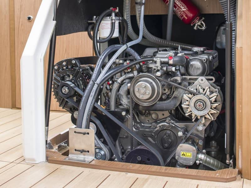
John Rushworth • 29 August 2019
Single Fuel Sailing
Most sailing yachts carry three fuels onboard: diesel, propane and petrol. It would be nice if you didn’t have to – for both safety and simplicity. And in fact that’s exactly what Ken Wittamore, Managing Director of Triskel Marine Ltd., has achieved with his Hallberg Rassy 42, named Armorel. Not only does Armorel use diesel as a single fuel solution; her electrical energy needs are primarily taken care of by Integrel – an advanced generator replacement technology. We’ve reported about the award winning Integrel before in the blog – Nigel Calder and the Integrel 9kW ‘Alternator on Steroids’ . The headline image above shows Integrel fitted to a Jeanneau Sun Odyssey 44. Let’s have a look at how single fuel sailing aboard Armorel, fitted with an Integrel system, comes together – utilising Victron Energy products to store and distribute all that power. A bit of history First a quick look to the past – Ken and Nigel combined have many decades, nay a few lifetimes of experience in the marine world. Nigel with his world famous books and articles, along with his various personal yacht projects – plus Ken with his own boat Armorel and his company Triskel Marine . Getting to the juncture of single fuel sailing with oodles of self generated energy; is one that is the culmination of such experience, the genesis of which can probably be traced back to the HYMAR project in which Victron also initially had a role. I won’t bore you with the details of how we got from there to here – suffice to say a diesel engine with Integrel generation and plenty of stored energy onboard has emerged as the best commercial solution for most yachts with demanding energy and propulsion needs. If you wish though, here is a link to the: Final Report Summary – HYMAR (High efficiency hybrid drive trains for small and medium sized marine craft). Subsequently and as a consequence of the HYMAR project, Nigel Calder was involved in the development of Integrel with the Triskel team. Fast forward to the present and Integrel is now a production item, with system design, manufacturer and installation all by Triskel Marine. Integrel has now been fitted to a number of vessels – all of which use Victron Energy products. They include Armorel – a Hallberg Rassy 42 (using just one fuel), Topaz – a Sun Odyssey 44, plus a brand new Lagoon 46, which uses 4 x Victron 200Ah, 25,6V Lithium Smart batteries in series/parallel giving 20.48 kWh of energy storage @48V, along with an 8kVA Quattro combined inverter/charger . Of course, subject to the vessel, not all require 8kVA inverter/chargers. Armorel in fact uses 2 x Victron MultiPlus 3 kVA inverter/chargers instead, along with the same battery setup as above – which is sufficient to achieve single fuel sailing in her case. Why use one fuel? The best person to explain this single fuel solution is Tom Pugh-Jones, Customer Service Manager at Triskel Marine. Here’s his take on the matter: “Firstly, getting propane off the boat increases safety levels onboard, as you’re no longer having to cook with a naturally colourless, odourless and highly flammable gas. A gas that can’t escape anywhere, save usually into the bilges; an explosion waiting to happen? Also, as many of our client’s cruise in different parts of the world, they have to adapt their gas configuration dependant on where they are in the world – not convenient. The alternative is electric cooking which is a game-changer, but it doesn’t come without its power demands. Armorel’s Techimpex Horizon2 gimballed induction stove, grill and oven – showing the 2,000W & 1,800W hob plates in action. Secondly, we’ve done away with the 4 stroke outboard tender engine, the reasoning behind this is two-fold, we don’t want to have multiple fuels – yet another flammable hydrocarbon – therefore electric simplicity is key. Also, 4 stroke engines seem to struggle more and more with modern fuels as there’s a higher level of bio-ethanol in petrol these days, which gums up carbs and makes them less reliable. Modern electric outboards are great, requiring less maintenance with a similar performance and they charge straight from a 230V socket. Torqeedo offer an excellent range of electric outboards. Their Cruise models range from 5 – 20hp . Torqeedo Cruise electric outboard. With an all-electric energy boat you have to plan less, as you’ve always got available power which allows you to be off-grid for longer. The only difficulty is the large amount of electricity needed, but with new technologies being able to generate, store and distribute large amounts of electrical power throughout a boat – this can now be achieved. Armorel at anchor, with no shortage of electrical power. Integrel whether at anchor or underway allows us to make the most out of our diesel engine and it’s spare capacity, by generating lots of energy – storing that in modern batteries that can easily accept and discharge large currents, quickly.” Integrel “Integrel to our mind is the future of power generation afloat, completely replacing your stand-alone generator by using spare capacity from your existing inboard diesel engine. Integrel uses smart new technology to generate up to 9kW of electrical power without compromising your engine’s performance. In fact, the system actively manages its output, so that the engine is always running at its most fuel efficient. Side view of a standard diesel engine with an Integrel Generator, fitted to Topaz, a Sun Odyssey 44. The battery bank on the right is a 48V bank, comprising of 4 x Odyssey PC1800-FT batteries. By using your engine for both propulsion and power generation, both tasks are delivered at optimum efficiency, resulting in overall fuel savings (in comparison to a separate generator and diesel engine) of up to 25%. One engine, two jobs, less fuel. Integrel Smart Controller aboard Topaz, a Sun Odyssey 44. Integrel is completely automatic, working in the background with no direct input from you. It requires no maintenance other than a periodic belt change, offering substantial savings on fuel and maintenance costs across its lifetime.” Integrel Monitoring aboard Topaz, a Sun Odyssey 44. Energy storage and distribution Of course it’s all well and good having an integrated smart generator, but without a method of storing and distributing that energy to create the power to run air conditioning, a stove, fridge/freezer, maybe a microwave, charge an electric outboard, plus all the usual nav and domestic demands of a modern yacht – well it simply couldn’t be done. That’s where Victron Energy come in. Here’s how such an upgrade works on Armorel. Click the image above to download a PDF of Armorel’s system schematic. With Integrel and the normal alternator – you have system power, stored energy and redundancy like never before.” Complimentary Victron Energy products Triskel Marine use a variety of Victron products in their installations including: Lithium Smart batteries Example – 4 x 200Ah Victron 25,6V Lithium Smart batteries being fitted to a Lagoon 46. Quattro Inverter/Chargers MultiPlus Inverter/Chargers Orion DC-DC Converters Example – Victron Orion DC-DC converters fitted to a Lagoon 46. SmartSolar MPPT – Solar Charge Controllers Lagoon 46 – integrating Integrel and Victron Energy power products. Conclusion Combing Integrel and Victron Energy products helps vessels achieve energy autonomy for Triskel Marine and their customers – which to my mind makes a lot of sense. Such a system gives you as much AC and DC power whilst away from a shore supply as it seems one could possibly need – and all with just one diesel engine, plus a single fuel solution if you wish. One engine, two jobs, less fuel. Single fuel sailing – simple and safe. If that appeals to you then why not check out the links below. John Rushworth Triskel Marine – https://triskelmarine.co.uk Integrel – https://www.integrelmarine.com Credits Thanks to Tom Pugh-Jones, Customer Service Manager at Triskel Marine, for the images and information used in this blog.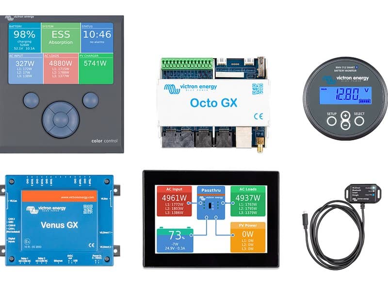
John Rushworth • 27 August 2019
Battery Monitors and Monitoring Solutions
Victron Energy have a comprehensive range of Battery Monitors, Battery Balancers, BMS and Shunt options, plus a wide variety of panel and system monitoring solutions (local & remote) such as the Victron GX product range for example. There’s also a range of complementary accessories . Amongst the many accessories are a range of Temperature Sensors , to name but one product group. Added to all this is the free and ever popular VictronConnect app, plus the VRM Portal (also free) – where device monitoring, product configuration, firmware updates and data can all come together. The beginning and the BMV range In this blog though I want to draw your attention to where all this integration started – the stalwart BMV range. The BMV range consists of products with BMV-7 in the model name; earlier versions had a 6 prefix. Below I highlight the differences between the various current models – so you can be sure you choose the right one for your application and budget. The range consists of: BMV-712 Smart (6.5 – 95 V, 1 – 9999 Ah, Bluetooth built-in, Auxiliary input) The models below, without Bluetooth built-in, we collectively refer to as the BMV-700 series: BMV-702 (6.5 – 95 V, 1 – 9999 Ah, Auxiliary input) BMV-702 [Black] (6.5 – 95 V, 1 – 9999 Ah, Auxiliary input) BMV-700 (6.5 – 95 V, 1 – 9999 Ah) BMV-700H (60 – 385 V, 1 – 9999 Ah) This BMV (Battery Monitor Victron) range are a group of high precision battery monitors. Their essential function is to calculate ampere hours consumed and the state of charge of a battery. Think of these monitors as your battery ‘fuel gauge’, with a time-to-go indicator and much more. Each model comes with a square bezel overlay (if you wish a square gauge look as opposed to round), a securing ring for rear mounting and screws for front mounting. Any model can be mounted in a panel of your choice with a 52mm (2.0 inch) aperture or in one of Victron’s optional bespoke wall enclosures. A 500A/50mV shunt, fitted with a quick connect PCB is part of every product package. Alternatives shunts are available if required: 1000A-50mV, 2000A-50mV, 6000A-50mV . All models come with 10m of 6 core UTP cable with RJ12 connectors and a power supply cable complete with fuse. The BMV range are all compatible with VE.Smart Networking . Note that although the BMV-702, BMV-702 (Black), BMV-700 and BMV-700H do not have Smart Technology built-in, they can all be updated to use it with the optional VE.Direct to Bluetooth Smart dongle . The only downside is that means the VE.Direct communication port is now in use for the dongle, so you cannot connect it to a Victron GX device as well. If you want Victron Smart Technology and GX device connectivity, then buy the BMV-712 Smart. If you don’t need the added functionality of the 712 Smart or are on a budget, then choose one of the other models to suit your needs. BMV-712 Smart This model is the latest evolution of our ever popular BMV range of battery monitors. It has the same functionality as the earlier BMV-702, but with the added benefit of integrated Victron Smart technology; which implements Bluetooth (as in many other Victron Energy products) – giving wireless communication between various products. Victron Smart technology simplifies system setup, monitoring and firmware updates using the free VictronConnect app. The **2 in the product name refers to the fact this product features a second input which can be programmed to measure the voltage (of a second battery), or battery temperature , or midpoint voltage. BMV-712 Smart product page BMV-702 The 702 has the same features as the 700 but in addition (just like the 712 Smart) it has an auxiliary input. This can be used to measure the voltage of a second battery, or temperature using the temperature accessory , or midpoint voltage. BMV-702 product page BMV-702 (Black) Just like the standard grey coloured 702 but with the black colour option. BMV-702 (Black) product page BMV-700 This is the base model for batteries in the 6.5 – 95 voltage range and battery capacities from 1 – 9999 Ah. Unlike the BMV-702 and BMV-712 Smart, the 700 the does not have an auxiliary input. BMV-700 product page BMV-700H The BMV-700H is the high voltage version (60 – 385 voltage range) of the BMV-700 (6.5 – 95 voltage range). The BMV-700H is supplied with a shunt mounting box. Note: The BMV-700H is suitable for systems with grounded negative only, as the battery monitor is not isolated from the shunt. BMV-700H product page Accessories & related products These are just some of the accessories and BMV related products that are key to battery monitoring and the good maintenance of your batteries. Others such as the GX GSM modem and the Smart Battery Sense can be found on the comprehensive accessories page . VE.Direct to Bluetooth Smart dongle (allows BMV-700 series models to use the VictonConnect app over Bluetooth, just like the BMV-712 Smart does with its built-in Bluetooth) Temperature Sensor (use the auxiliary input of BMV-7*2 models to show temperature on your BMV using this accessory) Wall Enclosures ( BMV or BMV + Color Control GX) BMV Wall mount enclosure BMV plus Color Control GX wall mount enclosure Shunts (1000, 2000, and 6000 A/50mV sizes which are alternatives to the standard 500A/50mV shunt supplied with each BMV) 6000A-50mV alternative shunt example Battery Balancer (equalizes the state of charge of two series connected 12V batteries, or of several parallel strings of series connected batteries) Victron GX product range allows expanded battery monitoring options, both local and remote, when used with a BMV (example GX device shown) VE.Direct cables (various lengths) to connect a BMV 7** to a Color Control GX VE.Direct to USB interface (connects several BMV 7** to a Color Control GX or to a computer) VE.Direct LoRaWAN – module (Connect your BMV directly to the VRM [Victron Remote Management] portal ) Conclusion I hope this blog has given some insight into our basic battery monitoring choices and how they can expand to cater for a plethora of system options. Oh! — and if you’ve read this far that includes (for the tinkerers amongst you) an option to join a Beta programme and also experiment with the GX range of open source software. Start here if that appeals to you. John Rushworth
John Rushworth • 13 June 2019
Sailing with Signal K
Pictured above is a screenshot from WilhelmSK (a popular Signal K app) showing just some of the information that can be displayed onboard your boat, when using Signal K and Victron Energy products together with Victron’s Venus OS. Venus is the software operating system used by the Victron GX product range . As many of you will know Venus can also be used with Open Source projects too. Various examples can be found with a search on ‘Rasperberry Pi’ here on the Victron blog . If you are not familiar with Signal K and the plethora of information that can be integrated from onboard boat systems, then this blog I published a year ago will serve as a primer – Signal K: Embracing connectivity with Victron Energy . Since publishing that blog, Signal K due to the passage of time has evolved even further and created a great deal of interest in the marine world in its own right – plus as a further consequence of my blog – this has led others to integrate Signal K with Victron Energy products. One such project (which takes everything to another level) is Stefanie’s sailing vessel Taku Moe, with its fabulous onboard integrated systems display and management. Sailing Vessel Taku Moe Taku Moe is a Bavaria 390 Lagoon and has gone through an extensive refit in recent times. Her crew consists of co-owners Stefanie and Heike. Starting next week they set sail from northern Germany for a four week trip from Schleswig into the east Baltic and Poland – and then next Spring their avowed aim is to head for southern Spain. From there the plan is to commence a circumnavigation of the Mediterranean, next cross the Atlantic and visit the Caribbean – later to go wherever the wind takes them over the coming years. Taku Moe – Bavaria 390 Lagoon Stefanie and Heike are highly qualified, competent sailors and Stefanie (if she’ll forgive me for saying so) is the major geek of Taku Moe’s crew. Who better to implement Signal K onboard… Implementing Signal K From here on, I’ve edited Stefanie’s comprehensive description of her project. Not because her words were lacking, merely it’s my attempt to make the best sense of our communication between a German that speaks English (but not as a native language) and an Englishman that doesn’t speak German. Here then is what Stefanie has to say: Project Aims & Challenges To have a single iOS App displaying many different values such as navigation, power and environmental data – all such data taken from the instrumentation aboard Taku Moe. This singular app to be served from a Signal K Node Server over wired and/or wireless, to seamlessly integrate the many different display protocols. Implementing this, there would be no need to have dozens of different apps to display the boat information – as previously the multiple devices couldn’t even talk to each other. A few years ago such project aims were not possible, as each equipment vendor relied on their own proprietary protocols – and in fact still do. That situation makes for a very unfriendly user experience and a significantly expensive one too – when you want to keep your instrumentation and equipment up to date. Fortunately this awful situation changed when some nice guys came together and started to develop Signal K. What is Signal K? Without going into too many technical details, let me quote from the developers themselves: “Signal K is a modern and open data format for marine use. Built on standard web technologies including JSON, WebSockets and HTTP, Signal K provides a method for sharing information in a way that is friendly to WiFi, cellphones, tablets and the Internet.” The many different protocols and Bus systems aboard Taku Moe are: NMEA 0183 and SeaTalk 1 (Raymarine Wind, Speed, Depth, Water Temperature) NMEA 2000 and SeaTalk NG (Raymarine Evolution EV-200 Autopilot, MFDs, B&G VHF, AIS, Air Temperature, Air Pressure, GPS, Fusion Radio) Modbus TCP (Victron Venus OS running on a Raspberry Pi) VE.Direct (Victron BMV-700, Victron Blue Solar MPPT 150/35) VE.Bus/CAN+MK3 (Victron MultiPlus C 12/1600/70-16 230V) Simarine Pico (protocol needs to be reverse-engineered to get data interfaced with Signal K) 1-Wire (external so called 1-wire sensors i.e. for temperature, humidity, pressure, tank levels) CAN Bus (interface between Signal K and NMEA 2000, allowing bi-directional flow of data) MQTT (to talk to Sonoff smart switches to switch on several devices like Radar, Windlass, Bow Thruster, Lights through the same app) TCP/UDP/HTTP/WS (Teltonika RUT950 Router, 2 x Raspberry Pi, iPhones, iPads, MacBook). Note – both Pi can basically replace the router as they are able to serve as that too, but as I already had the Teltonika I’m using it. Teltonika RUT950 Router As one can see, all that above is a whole lot of different protocols and buses coming together. At first glance one can assume that wiring such a system ends up in a total mess. Not even close, because thankfully the router aboard makes it easy to connect most of the devices through a simple Ethernet cable. The rest is straightforward 12V DC wiring to sensors, or Plug and Play (PnP) between the different buses. DC to DC Converter How do I get there? Not easy to answer. In my view there are 3 solutions. 1. To default to commercial offerings and with that quite expensive solutions. It is possible but requires some engineering. I’m not an engineer nor do I want to spend a whole lot of money for a system whose half life period is less than a few years year (thinking of all the MFDs I have spent money on in the last years…). 2. To revert back to what sailing was a few decades ago and quit with all the smart things. Yes, that is possible, but I grew up right in time to experience how the internet seemingly came out of nowhere. Also I’d been playing with Arpanet through DIY modem/couplers and blue boxing (110 baud, can you imagine?!) when the phrase ‘computer network’ was not even familiar to most. As such I became addicted from the very first day, so no option to go back in time for me! 3. To do it the hard way even when you have no idea about all this stuff, which means: to grapple with at least the basics of protocols, interfaces, trying to remember what Linux is, read the ‘effin’ manuals and bring it all together. That saves money, a lot in fact and keeps the brain busy – which at a certain age helps! Luckily there are friendly communities at Victron, Signal K etc., all who are extremely helpful and patient to support you in this process if you don’t get it the first time around. Vital system components WilhelmSK – The Swiss Army Knife to achieve my goal. (WilhelmSK is a highly customisable boat instrument display that uses the Signal K protocol to show information from your boat’s sensors on your iPhone, iPad, Apple Watch or Apple TV. Scott Bender, the author of WilhelmSK, is also one of the main developers and contributors to the Signal K Node Server). Raspberry Pi – One Pi hosts OpenPlotter/Signal K/Homebridge/Node-Red, InfluxDB, Grafana and is the brain which brings it all together. The second Pi runs Victron Venus OS – the heart of the electrical system. 2 x Raspberry Pi Apple TV, HomePod or iPad/iPhone required for smart switches to become accessible via HomeKit into Signal K/WilhelmSK – and all this fancy stuff you can find under “protocols and bus systems”. Sonoff Smart Switch & tablet with WilhelmSK and OpenPlotter Advantages of Signal K, WilhelmSK, Node-Red and Venus OS Open Source except for WilhelmSK, which doesn’t cost a fortune (20 Euros I think). This all means a lot of support through a large community of developers and users. Plenty of updates and upgrades with the implementation of new features (if it makes sense) and bug reports from users. WilhelmSK is highly customisable, showing all the values one can think of. Be it electrical data from the Victron Product line, environmental data from sensors, switches from HomeKit or navigational data from the NMEA network – bi-directional. That means I can control my Victron devices or smart switches, the Raymarine Autopilot, my Fusion Radio, whatever. And if you have influxDB/Grafana setup, you can store all the data for history or real-time display all nicely presented. Have a new device or sensor? No problem as long as the protocol is known. Then simply define your own Signal K path and voila, it shows up on WilhelmSK. You’re completely free in setting up gauges, digital, analogue or as a bar. You hate digital numbers and love the new Venus HTML5 app from Victron? Again, no problem. Use a so called Web gauge within WilhelmSK and get the benefits of this beautifully designed app within another app. Remote Control. Have access to all your data and switches through the internet. Control your Victron devices whenever and wherever you want. Turn the Multiplus Charger on when the batteries run low. Check bilge sensors inside the boat for possible water ingress or get notified by SMS/Telegram/Messenger/Twitter whatever program you like to be notified in real time that your boat is possibly about to sink or gale force winds are pounding your mooring telling you to go and check it. This all requires access to a GSM network, which is setup in my case through the Teltonika router with SIM card via (and highly recommended) a VPN. Remote Console example Local Venus Console on Raspberry Pi System schematic The schematic above is how everything works together. Not yet marked is the NMEA 2000 network, which is connected to the signal K Node server via USB. Click image to enlarge. Some of the Victron products fitted to Taku Mo Is there anything lacking? As of yet, no, not really. When Victron decided to collaborate with the Signal K development team, a whole new world opened up making many things possible that I’d only dreamt of. And this collaboration is helping both, Victron and Signal K to benefit from it, not to mention the user. When talking about the Internet of Things (IoT), then a solo effort quickly becomes a one-way street. I’m really surprised how easy it was in the end to set this all up, although at times I had plenty of headaches. It took a long time to decide whether I wanted to go this route or leave it as is. But once started, it quickly developed. A no-brainer when the first Victron data appeared on the iPad screen. It makes me want more of it. Plenty of new ideas coming up. I think that is part of it and that keeps it all moving – the bread and butter for the developers. Additions 06/04/2019 – Added switches to WilhelmSK. Now I’m able to add switches (which are compatible but not certified with HomeKit) to WilhelmSK and can switch whatever I want – such as Windlass main switch, Bow Thruster main switch, Radar and a few others I have in mind. Switches are Sonoff Basic for 230V devices hooked up to the Multiplus and Sonoff 4ch Pro R2 (powered by 12V DC) for 12V devices. Sonoff are flashed with Tasmota firmware to make them compatible with Apple HomeKit through Homebridge . WilhelmSK recognises these switches as soon as they appear in HomeKit. Exciting stuff. Installation on Taku Moe – Day 1 29/04/2019 – Today I started with the installation. Both PI’s are now connected via Ethernet to the router. Next step was the firmware update on the MultiPlus to version 459. That was a flawless task. See Victron Professional . Then connected the Victron Interface MK3-USB to the Venus Pi as well as two VE.Direct to USB Interface . One for the BMV-702 and another one for the BlueSolar 150/35. Need another one for the new SmartSolar 75/15 (added a 4th Solar Panel, which unfortunately is only 135Wp. The 150Wp was out of stock and got replaced by a 165Wp panel, which cannot fit on the bimini). Booted into the Venus, setup the connection to the router and shutdown the demo mode. Without doing anything the system recognised the Multiplus, Blue Solar and BMV. Need to do some further adjustments for my specific system. But it basically works “out of the box(Pi)”. Installation finished! 27/05/2019 – That was more work than I thought, but in the end everything works as expected. Had some trouble understanding how DVCC affects the System but now the DVCC documentation has been improved, so I think I have got the hang of it. D-Bus data is now available via VRM, LAN, WiFi, wherever I want. System is accessible also through VPN from home. Can switch the Multi on/off from home and of course see and remotely control all available data, be it Victron stuff or boat related data. The most fun thing is the Water Heater, which I can switch on from home as well! That was lot of fun and a learning experience throughout the preparation and installation process – but I’m so totally excited to have it all running… Stefanie Click logo to take you to the Taku Moe Website – (in German but a good inline translation to English if using Google Chrome). Conclusion My thanks to Stefanie for all her hard work in communicating her project to me and in supplying the text and images for this blog. Whilst I can’t claim to have done the hard work – hopefully this blog (and my original – Signal K: Embracing connectivity with Victron Energy one) helps you see how collaboration between individuals and communities has a collective and quite profound effect in bringing people together and improving the breed – something that Matthijs Vader of Victron Energy had envisioned right from the start with Victron’s Signal K collaboration. Long may that continue… Why not visit the Victron Community ? In closing I wish Taku Moe and crew, all Set Fair! John Rushworth Resources & Links Taku Moe website – https://www.sailingtakumoe.de Taku Moe on Facebook – https://www.facebook.com/TakuMoe Taku Moe Signal K blog (inc more resource links) – https://www.sailingtakumoe.de/2019/06/05/signal-k-wilhelmsk-taku-moe-becomes-smart/ Taku Moe on Victron VRM – https://vrm.victronenergy.com/installation/35603/dashboard Signal K website – http://signalk.org Signal K on GitHub – https://github.com/SignalK Signal K on Google Groups – https://groups.google.com/forum/#!forum/signalk Signal K demo node server – http://signalk.org/demo.html Signal K on Facebook – https://www.facebook.com/signalk.org Applications & Solutions with Signal K support – http://signalk.org/solutions.html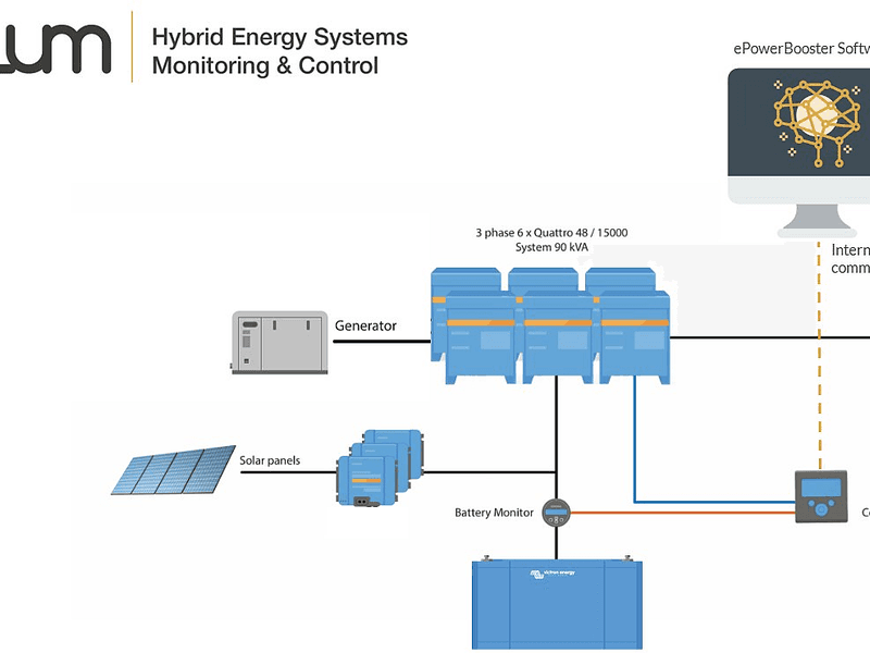
John Rushworth • 11 April 2019
ePowerBooster: Saving fuel in hybrid energy systems
Karim El Alami and Cyril Colin met at UC Berkeley in California, whilst studying for their degrees in civil and environmental engineering. Their drive was to develop software to manage hybrid energy systems and reduce operators’ bills. In this short case study we focus on a hybrid energy system using Victron Energy components and ePowerBooster software – a new cloud-based controller built by Elum Energy, the company Karim and Cyril founded after their university days. Introduction It is often hard to define fixed genset start and stop rules that stay optimal throughout the year. For example, during the sunny season, charging your battery at night with a genset may lead to lost solar energy that could have been stored the following day. This is the issue that ePowerBooster solves. Rather than using a fixed set of parameters, the solution continuously monitors the daily PV yield and load profile – then adapts the start/stop rules. This solution is surely of interest for any site where fuel costs are a consideration. The ePowerBooster especially helps in monitoring and optimising projects with large and/or multiple systems, where minimising operational costs are important. Potential users can sign up to the free Victron VRM portal without installing any additional hardware and take advantage of a free 1-month trial of ePowerBooster. The opportunity then exists to save up to 15% on fuel costs. About Elum Energy Elum Energy’s headquarters are in Paris, France. They specialise in the development of control systems designed for hybrid and battery-based solar projects. Their microgrid monitoring and control solutions are considered reliable, efficient and highly compatible. They can be installed on projects ranging from 100kW to 20 MW. To date systems have been installed by leading renewable project developers in more than 10 countries. Case study: Ziragula – Rural electrification microgrid – Tanzania The ePowerBooster has been deployed since January 2019 on a site developed by PowerGen in Tanzania, where it enables the electrification of rural communities. PowerGen started using the ePowerBooster on their PV/Battery/Diesel hybrid system without making any changes to their pre-existing hardware configuration. On this islanded hybrid site, eLum’s ePowerBooster algorithm optimises generator cycling schedules in order to maximise solar energy usage and reduce generator runtime & fuel consumption. Compared to fuel consumption with native Victron systems, the addition of ePowerBooster reduced fuel costs by 8% during the first month. An example – on the day shown in the graph below, genset consumption was 7.5kWh compared to 18kWh. This saved around 4 litres of fuel on that particular day. Click image above to enlarge graphs. To learn more, see the ePowerBooster PDF Datasheet . ePowerBooster and Victron Energy integration The video below shows how Elum Energy’s ePowerBooster cloud-based controller connects with Victron Energy’s control and monitoring systems. Conclusion Anything that helps to reduce the use of diesel fuel and save money can’t be a bad thing. We are delighted Elum Energy have chosen Victron Energy system components and the VRM Portal to work in association with ePowerBooster. For additional information about ePowerBooster, please email contact@elum-energy.com My thanks to Yoann Le Fol (Victron Energy Sales Manager for West and Central Africa, Madagascar, Comoros) for making me aware of this project. John Rushworth Links Website – https://elum-energy.com/en/home Facebook – https://www.facebook.com/eLumEnergy Twitter – https://twitter.com/eLum_energy
John Rushworth • 20 March 2019
Bigger batteries: More Ah needed?
It’s a complaint I often hear – ‘My leisure batteries aren’t big enough and they keep going flat quickly.’ This blog is primarily aimed at motorhome, RV, campervan, caravan, commercial vans, boat and yacht owners – concerning the issue of more battery capacity needed, with different ways to achieve that. When running out of amps many assume their leisure batteries have failed, yet often this is not the case. It’s more how, where, when and what the batteries are used for. Things like cold temperatures, high loads and deep discharges affect battery capacity (Ah) and life. And certainly these days we often place greater demands on leisure batteries than the original system design may have intended. This presents a dilemma. Running out of Amps A typical small yacht, that was built some years ago, might have a 90Ah leisure battery and a 80Ah starter battery on a split charging system. The battery boxes, cabling, charger and alternator will all have been sized accordingly. But these days you are running more equipment, often at higher loads and need therefore more battery capacity – so you don’t have to start the diesel engine to inefficiently charge with the alternator, when away from shore power. Maybe you start off by adding a small solar panel, but even that is not enough. Now you are faced with redesigning the system to get more capacity. Costly in both time and effort. The same goes for motorhomes. For instance, my recently acquired 12 year old Hobby T600 motorhome (shown in the headline image) has 1 x Sonneschein gel leisure battery 78Ah (C20), 65Ah (C5) and a Duracell 74Ah starter battery. That gel leisure might be fine for folk with small 12V needs that spend 90% of their time on hookup, use gas for cooking, heating and 230V for the fridge – and rarely go off-grid. But as I soon discovered, switching on a number of 10W lights and running the gas heating fan overnight – it quickly depleted the leisure battery whilst away from shore power. No surprise there you might say, but once again you find yourself pondering more power and energy from the leisure battery or batteries. In the meantime updating to all LED lighting at 1/10th of the power consumption has helped, plus changing to a Victron MPPT from the old PWM one for my 100Wp solar panel means it performs more efficiently and improves solar harvest. The MPPT in the top right of the photo below is networked using a Smart Battery Sense , as the ambient temperature of the MPPT compared to the leisure battery temperature can be as much as 10 ° C difference. Doing this ensures temperature and voltage compensated charging; a factor that also needs to be taken into account for cold weather charging . Upgrading to LEDs and a MPPT Solar Charge Controller The above mods though didn’t fully solve the problem – as I wanted to charge my electric bicycle off-grid, plus my friends’ bikes and make ‘electric’ toast, use an electric toasted sandwich maker, boil a small 600W kettle, plus run my laptop and other device chargers from AC power. That meant an inverter. Not something everyone requires, but having AC and DC electricity can be very useful. The solution – just get bigger batteries? A larger Ah battery solution might sound obvious but once you start looking into it you discover you need extra space, the current battery box or boxes are too small, weight might be an issue, the cables are too thin to take higher current, the charger is no longer big enough, plus where to locate an inverter if needed. If that’s not a project you can do yourself there will be an expensive hourly rate to get a technician to upgrade your system. There has to be a simpler way. Fortunately most modern boats and vehicles, to get more kWh and Ah, generally have larger and often paralleled batteries. Personally I prefer a large monobloc battery (say 220Ah) or smaller ones in series to give the equivalent Wh of energy, as that is considered safer than parallel. Need more batteries for a new build, then series the largest monoblocs you can get and run at say 24V or 48V with DC to DC step-down to 12V. That assumes you have a suitable alternator of course. Regardless, it’s easy to see that getting more energy and power with an upgrade is not as easy or as inexpensive as it might first appear, when compared to designing a new build. Insight tip: Energy vs Power if those terms and their differences are not familiar to you. Compared to my older vehicle my friend’s nearly new motorhome has both more energy and power available, with 3 x 95Ah (C20), 85Ah (C5) Varta AGM batteries giving a total of 285Ah @12V at the 20 hour C rate, where C refers to the capacity and the 20 or 5 is the number of hours to deplete the battery to 10.8V (flat). Faster discharges shrink the Ah – as you can see by that 5 hour Ah rating which is related to the load. Note those Ah capacities for those C rates are when a battery is used on its own, not when paralleled as running in parallel with more Ah improves any reduction in Ah due to higher than standard 0.05C loads. These ratings referred to are all at a temperature of 25°C, which is the standard rating temperature. Below that temperature, battery Ah decreases further as it does with age. So, what starts out as 285Ah (of which 50% is generally accepted to be the economic discharge usage) is now 285/2 x a higher load than the standard rating of C20 (or 0.05 x Ah) of say 0.1C (28.5A discharge) at 25°C (an inverter type load), which then shrinks the Ah by a factor of around 0.84 as shown below – 285Ah reduced to 240Ah. Temperatures of lower than 25°C and age will shrink that Ah even further. I have assumed a Peukert exponent of 1.25 for this 285Ah lead acid AGM battery bank. The Peukert Calculator used in the screenshot above is a spreadsheet in Microsoft Excel format that allows you to enter the battery capacity and Peukert’s exponent. It then selects various discharge rates, calculates run times (note that the times are in decimal hours i.e. 1.5 hours is 1 1/2 hours = 1 hr 30 minutes), Peukert corrected amps and total amp hours available at the different discharge rates. It also incorporates a graph of discharge current against available amp hours. The extent of the effect may surprise you. The calculator, written by Chris Gibson, is the copyright of SmartGauge Electronics and is available here . Now let’s put in an ageing factor of 0.8 (so you still get what you need even when the batteries get older) and suddenly the available Ah is 285 x 0.5 x 0.84 x 0.8 = 95.76Ah or 12V x 95.76Ah giving 1.15kWh of useable energy compared to a stored C20 energy of 3.42kWh 25°C. No wonder folk think their batteries need replacing or they need more Ah! The above applies to lead-acid battery technology, lithium is far more forgiving with a Peukert of around 1.05. You can read about LiFePO4 vs AGM technology in a recent blog I did concerning Victron Energy’s new SuperPack batteries . Choices & a different approach Contemplating getting more useable Wh for my motorhome I started looking at upgrading my standard system, but the leisure battery is under the passenger seat with restricted space, the wires run under the floor and inbetween bulkheads, plus I needed a bigger charger, not to mention an inverter to charge my electric mountain bike. Maybe the alternator would need to be upgraded too. Anyhow hopefully you get my point – it was simply not realistic to modify the standard system either in terms of cost or effort, plus the leisure battery happened to be brand new. My solution was to create a separate, standalone, portable ‘Powerpack’ – similar to a powerbank for mobile phones. It was something I could put together easily in the comfort of my workshop (living room in fact). Admittedly I went somewhat over the top – but that is as much to illustrate what can be achieved and how space and weight criteria can force a choice. Ideally I prefer Lithium-iron-phosphate (LiFePO4 or LFP) to our Lithium-Ion HE Battery and Lynx Ion BMS, as LFPs have a higher cycle life and the HE BMS is quite sizeable taking up extra space. However in this particular case due to the actual dimensions of the space available and weight considerations I had to use the HE NMC type. Fortunately my inverter loads are low too, so the HE type could accommodate them, whereas on my boat LFPs are better due to that chemistry’s higher continuous discharge rates. In fact were weight and size not an issue then AGM’s would have been okay too, as of course would the all in one design of the Lithium SuperPack range – having no need of an external BMS taking up extra space. You’ll see what I mean in the table later in this blog. Your requirements might be more modest too in terms of battery type, power and size – so besides my own Powerpack build I’ll include other versions in a later blog, which will show how to size an inverter for charging electric bicycles off-grid as an example. For now I’ll leave you with some before and after photos of my solution, which simply goes inline with the hook-up shore power prior to the RCD/Consumer unit in the van. Unplug two male/female 16A commando type plugs/sockets and the original system is back to normal and you have a Powerpack for use elsewhere. Using this system my standard leisure battery is always full off-grid, either charged from my Powerpack or solar, plus there’s increased energy and power available for the needs mentioned earlier. The planning stage Pretty lights and LED momentary start switch. USB GPS to set a Geofence when parked. Testing – electric bicycle battery charging Phew, got the measurements right… 16A Commando plug/socket connections top right, allows simple inline connection from the back of the shore hookup and prior to the RCD/consumer unit. And just enough room for the electric MTB in the motorhome garage… Lead vs Lithium Having recently written about Victron’s new LiFePO4 SuperPack range along with a comparison to AGM, now seems a good time to compare lead vs different lithium types – so you can see why in this case weight, dimensions and energy density were more important than cycle life and better (higher) discharge C rates (power). 60Ah 12.8V LiFePO4 SuperPack 90Ah 12V Lead AGM 100Ah 25.2V HE NMC 200Ah 25.6V LFP- Smart Weight 9.5kg 27kg 15.7kg 56kg Size (mm) (l x w x h) 229 x 138 x 213 350 x 167 x 183 362 x 193 x 214 317 x 631 x 208 Useable energy @ 25°C 614Wh 540Wh 2,016Wh 4,096Wh Cycle life 2,500 cycles 600 cycles 2,000 cycles 2,500 cycles Cost x 2.5 (approx) x 1 x 2.5 (approx) x 2.5 (approx) Notes for the table above: Useable energy and cycle life are based on 80% depth of discharge for LiFePO4 and 50% for AGM, these being considered the most economic use of those battery types. The NMC lithium can be discharged to 100% in ‘Performance mode’ albeit at the cost of cycle life, giving more useable kWh than the 80% DOD shown in the datasheet and in the table above. 75% is considered the ‘Default mode’, 100% is ‘Performance mode’, all of which can be adjusted by your dealer with the Lynx Ion BMS tool. Higher loads with lead will further reduce available Wh ( Peukert’s Law ) when compared to Li-ion. Capacity is also reduced for all types by temperatures below their 25°C temperature rating ( see the respective batteries and datasheets ) Conclusion With no modifications to my standard motorhome system, other than the inline connection, this drop-in modular build has proved a great way to get more Ah. Lithium batteries are not essential though, subject to your needs, but in my case using NMC Lithiums as opposed to my preference for LiFePO4 was necessary – due to the required location of the pack and weight. Using a lead based system was out of the question as it would have loaded the back axle way too much and there would simply not have been the space to accommodate all that dead lead, let alone my eMTB. Full specifications of my 200 Ah NMC build, along with other ‘Powerpack’ options and how to size an inverter for a required load, such as electric bicycle charging – coming in another Victron Energy blog soon… If you have any comments about my ‘Powerpack’ build I’d be pleased to hear from you in Disqus below. For technical questions please ask me or indeed others on the Victron Community site. John Rushworth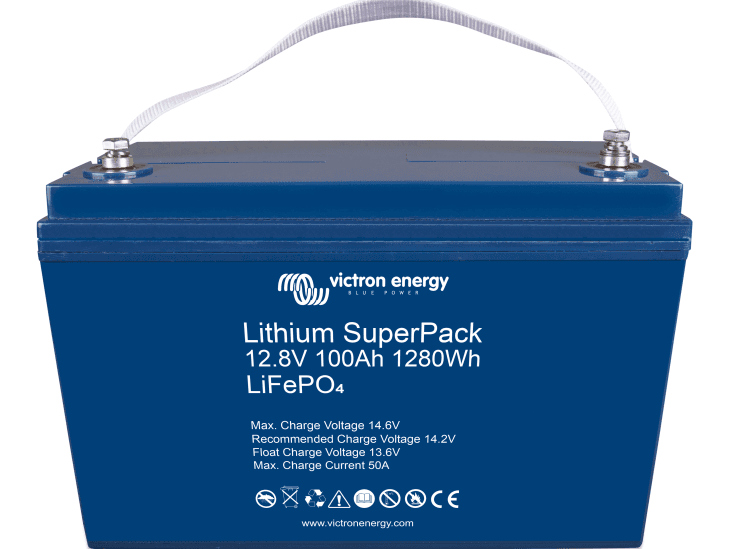
John Rushworth • 26 February 2019
Lithium SuperPack batteries – an all in one solution
These new Lithium-Ion, LiFePO4 chemistry batteries are often an ideal replacement for many 12V and 24V marine, automotive, caravan, motorhome, work vans and similar battery applications. It might even be for an overland motorcycle if using the smallest 20Ah version; to recharge a camera, phone or laptop for instance. Other examples – take a typical small boat or van which may have a 110Ah to 220Ah lead-acid leisure battery for light continuous loads such as lighting, laptops, phones, instruments, powering a diesel heater, a fridge etc. And for shorter term loads maybe add a small inverter to charge power tools, run a small microwave or travel kettle for example. Using one SuperPack battery it matches well with the Phoenix Inverter VE.Direct 250VA – 1200VA range. Maybe you’ll add in around 100 to 200Wp of solar panels too using a small MPPT . Regardless of the use, whichever SuperPack you choose it’ll be lighter than lead, can be smaller if you wish or give you more Wh in the same space – plus give you around 5 times the cycle life. The main difference to Victron’s other lithium offerings are the SuperPacks keep everything in one package, by having an integrated BMS and safety switch built-in. No additional components are needed as the internal switch will disconnect the battery in case of over discharge, over charge or high temperature. Simple, compact and safe. If you are considering a new battery don’t immediately discount Lithium as being too costly. Whilst it is true that the capital cost of Li-ion is greater than that of quality AGM or Gel batteries – it is also true that the cost of ownership can be less than lead acid types. Much depends on your application, but rest assured – life with Li-ion is far less hassle than lead. Over the last 8 years on my sailing yacht I’ve run AGM lead leisure batteries and Lithium-Ion propulsion batteries. Initially it was AGM for propulsion before discovering the effectiveness of Lithium. That journey taught me a lot about loads, capacity, cost and battery life – it’s one of the reasons why I think we’ve reached a tipping point and why these new SuperPack batteries may just be the ticket for your next project or battery replacement. If in the first instance you are unfamiliar with AGM vs Lithium, then here’s a blog that explains that. When to use a SuperPack? Every battery size and type has it’s own particular use. For instance you may use the Lithium battery 12,8V & 25,6V Smart in quite different applications to the new SuperPack range. So, where to use the SuperPacks? When it comes to replacing lead acid type batteries such as AGM and Gel in many applications, the SuperPack range can be considered the next generation after lead – making it far easier to replace lead with lithium. The only caveats being replacement is down to certain parameters being met, namely – Capacity (Ah), Voltages (12.8V & 25.6V), Discharge and Charge currents (C rates). Do in that case be sure that your chosen replacement fits your criteria by checking the datasheet and be aware the SuperPacks can be connected in parallel, but not in series. Hence in that case you would consider the other Victron lithium products named above. The Lithium SuperPack Victron Energy’s recently introduced Lithium SuperPack range comes in the following capacities and voltages: 12.8V & 25.6V Lithium SuperPack batteries: 12.8V – 20Ah 12.8V – 60Ah 12.8V – 100Ah 12.8V – 200Ah 25.6V – 50Ah These SuperPacks will give you 2,500 cycles to 80% depth of discharge at 25°C, much more than lead. Comparison: SuperPack 60Ah LiFePO4 vs 90Ah AGM Let’s compare the 60Ah Li-ion to say a typical 90Ah AGM battery discharged to the commonly accepted economic cycle life of 50% discharge for lead. That would give us 600 cycles at that DOD for the AGM compared to 2,500 at the even deeper discharge of 80% for the LiFePO4. Already you can see you may need to replace your lead-acid type battery 2 to 4 times as often as the Lithium. Of course loads, operating conditions and calendar life have to be factored in too. Regardless you get the idea – Lithium does more and lasts longer. The benefits of Lithium don’t stop there though. Whilst LiFePO4 chemistry is considered the safest of them all, it’s worth considering other factors too to decide whether the reduced weight and volume of say NMC is of more importance for your application than LiFePO4 for example. Victron Energy do both types. 60Ah SuperPack 90Ah AGM Weight 9.5kg 27kg Size (mm) 229 x 138 x 213 350 x 167 x 183 Useable energy @ 25°C 614Wh 540Wh Cycle life 2,500 cycles 600 cycles Cost x 2.5 (approx) x 1 Notes for the table above: Useable energy and cycle life are based on 80% depth of discharge for Li-ion and 50% for AGM, these being considered the most economic use of those battery types. Higher loads with lead will further reduce available Wh ( Peukert’s Law ) when compared to Li-ion. Capacity is also reduced for both types by temperatures below their 25°C temperature rating ( see their respective datasheets ) Make what you will of the above and whilst you are pondering the pros and cons don’t forget to take these additional factors into account for the comparison above. Shipping: If you are replacing your lead from 2 to 4 times as often as Li-on and the fact that the lead weighs around 3 to 4 times as much (depends on Li-ion chemistry used) – then do consider the extra shipping costs. Voltage stability: The voltage profile is far flatter for Li-ion compared to lead. Voltage sag: Subject to the load, voltage sag with lead is significant compared to Li-ion. Li-ion has much faster charge times and if charging from a generator it saves on generator runtime. Other factors to consider Is the above enough to convince you of why Lithium might be a better alternative than AGM or indeed Gel? Personally I’m sold on Lithium, but if you are not here’s a few things further to consider: A lead-acid battery will fail prematurely due to sulfation if it operates in deficit mode for long periods of time (i.e. if the battery is rarely, or never at all, fully charged). It will also fail early if left partially charged or worse, fully discharged. By comparison a Lithium-Ion battery does not need to be fully charged. This is a major advantage of Li-ion compared to lead-acid which needs to be fully charged often to prevent sulfation. Efficiency. In several applications (especially off-grid solar), energy efficiency can be of crucial importance. The round-trip energy efficiency (discharge from 100% to 0% and back to 100% charged) of the average lead-acid battery is 80%. The round-trip energy efficiency of a Li-ion battery is 92%. The charge process of lead-acid batteries becomes particularly inefficient when the 80% state of charge has been reached, resulting in efficiencies of 50% or even less in solar systems where several days of reserve energy are required (battery operating in 70% to 100% charged state). In contrast, a Li-ion battery will still achieve 90% efficiency even under shallow discharge conditions. Make the switch? Are you ready to make the switch from Lead to LiFe? If you’ve considered all the above I suspect you might be. And if you need more useable Ah why not run the sums on say a 100Ah Lithium SuperPack vs 220Ah AGM using the process I have above. Or indeed a 200Ah Li-ion SuperPack vs your choice of lead. Don’t forget too that Lithium has little or no Peukert effect when compared to Lead types. This is especially important when considering loads with lead-acid higher than 0.05C (Battery Ah divided by 20 or Ah multiplied by 0.05). In other words for a 100Ah AGM with a Peukert of 1.24 and discharging at 0.25C (25 Amps in this case – which is 5 times the 20 hour rate) there will be significant reduction in capacity – as there will be at colder temperatures too. Li-ion has a Peukert of 1.05 when compared to lead’s 1.24 factor. So – if you were discharging that 100Ah lead at 5 Amps (the 20 hour discharge rate at a temperature of 25 degrees centigrade) then the full capacity of 100Ah is still availaable and it’s not shrunk due to Peukert. But now if it were 0.25C, it’ll be around 80% of that original 100Ah capacity – or less, subject to load type and duration. The bottom line is you no longer have the Ah you purchased, whereas with Lithium there is little to no effect, helped by a lower Peukert and good voltage stability. That is especially important with constant inverter loads – a place where lithium shines. If you want to learn more about Peukert and run a spreadsheet to see such effects, then I have found this link most helpful. Finally and one I’m always grateful of is vastly reduced charge times, no more waiting for hours of lead absorption charging to get from 80% to 100% SOC. Conversely Li-ion flies up to around 98% SOC in bulk with those last few percent in absorption to fully balance the cells – and unlike lead you don’t always have to fully charge to 100% as often. Note that your 12V charging system needs to accommodate 14.2V – 14.4V ‘absorption’ and ‘13.5V’ float. If charging from an alternator also note the maximum continuous charge currents for the 12.8V range, by checking the datasheet. Downsides Not wanting to sound too evangelical, we also need to consider the few downsides of Li-ion. Higher upfront cost and to some extent higher capital risk. Charging is restricted to the +5°C to +45° range, subject to an internal means of blocking the charge source when the temperature is below +5°C. Note this is currently automatically possible with Victron MPPTs when used in conjunction with the Smart Battery Sense for instance. Other products are being worked on to achieve this too and documentation to that effect will be updated in due course. The SuperPack (unlike other Victron Lithiums) is not designed for series connections. The peak and maximum continuous discharge current of the SuperPack range is not as much as some of our Lithium batteries as its related to the BMS and the disconnect being internal to the battery – so do check the datasheet to make sure the current peak and discharge ratings suit your needs – or choose from the Lithium battery 12.8V & 25.6V Smart range, or build a parallel SuperPack bank. Conclusion Whatever your decision when purchasing new batteries, maybe it is time to give the Lithium SuperPack batteries a chance. There’s LiFe after Lead you know – but as I’ve shown that all depends on what you want to achieve. Is it less weight, less volume, maybe it’s capacity or voltage or any of the multitude of factors that go into choosing a battery system. Whatever you choose Victron have plenty of choice – with a large range of battery types and sizes: https://www.victronenergy.com/batteries John Rushworth
John Rushworth • 09 January 2019
Lead acid battery charging in cold weather
This blog covers lead acid battery charging at low temperatures. A later blog will deal with lithium batteries. Charging lead acid batteries in cold (and indeed hot) weather needs special consideration, primarily due to the fact a higher charge voltage is required at low temperatures and a lower voltage at high temperatures. Charging therefore needs to be ‘temperature compensated’ to improve battery care and this is required when the temperature of the battery is expected to be less than 10°C / 50°F or more than 30°C / 85°F. The centre point for temperature compensation is 25°C / 77°F. Cold weather also reduces a battery’s capacity. This is another factor that needs to be taken into consideration, along with the load and charge rate compared to the battery capacity (Ah). Both of these factors affect the correct and consequent sizing of a battery for your particular application. Battery capacity in Ah is usually quoted as a 20 hour capacity rating at 25°C. The discharge rate or load can be written as 0.05C where for example C is the load factor of the 20 hour rated battery capacity at 25°C. Worked examples: If a 100Ah 20hr rated battery then a 0.05 load would be 100 x 0.05 = 5 Amps or 100/20 which is also a 5 Amp discharge rate over that 20 hour period. A 10A load on a 100Ah 20 hour rated battery would therefore be a 0.1C discharge rate, a 0.2C discharge rate on a 200Ah would be 40A and so on. C ratings also relate to charge rates as well as discharge rates. When buying a battery you may see its Ah quoted at 20 (the standard rate), 10 and 5 hour rates so you can see how load ‘shrinks’ the Ah. Some even quote at 25 hour rates, which often fools people into thinking they are getting a bigger battery than standard. To recap – capacity reduces at low temperatures, as it does for higher discharge C rates above the 0.05C 20 hour rate. This reduction in capacity due to higher discharge rates is due to Peukert’s Law . Graph showing the effect on battery capacity due to temperature and load: Also with regard to temperature be careful not to let your lead acid battery freeze. The freezing point depends on its state of charge and the specific gravity of the electrolyte. Without getting into the complexities, suffice to say maintain the battery in a fully charged state, as at low states of charge the electrolyte is more water like and freezes earlier than in a fully charged state. Lead acid battery differences Lead acid batteries come in a variety of types: Wet lead with the ability to top up each of the six cells with de-mineralised water. The so called ‘sealed’ wet lead leisure or rather maintenance free battery. These cannot be topped up and often have a green go or red no go cell inspection indicator. AGM (Absorbent Glass Mat) valve-regulated lead-acid (VRLA), where the electrolyte is absorbed in a glass mat. Similar to the AGM, but the electrolyte is held in a Gel. All of the above are however lead based (as opposed to lithium) technology. Besides lithium batteries Victron Energy sell VRLA AGM and Gel monoblocs (6 x 2V cells in series) due to their superiority over wet lead monobloc types. Victron’s range consists of: Gel (Better cycle life than AGM). AGM (Better than Gel for higher loads and well suited for use with inverters). AGM Telecom. Designed primarily for Telecom applications, but also excellent ‘footprint space savers’ for marine and vehicle applications. AGM Super Cycle (Best if frequent discharge to 60-80% DOD is expected). Lead Carbon Battery (Improved partial state-of-charge performance, more cycles, and higher efficiency). Additionally Victron also sell specialist lead acid type batteries. OPzV 2V individual battery cells. Long life, high capacity gel. OPzS 2V individual battery cells. Long life high capacity flooded tubular plate batteries for specialist solar applications. Temperature compensation and charging Now we know about the kind of batteries, capacities and loads we are dealing with, we need to put some numbers together for temperature compensation and charging. The recommended temperature compensation for Victron VRLA batteries is – 4 mV / Cell (-24 mV /°C for a 12V battery). Besides accounting for cold weather charging the charge current should preferably not exceed 0.2C (20A for a 100Ah battery) as the temperature of the battery would tend to increase by more than 10°C if the charge current exceeded 0.2C. Therefore temperature compensation is also required if the charge current exceeds 0.2C. How to achieve temperature and voltage compensated charging There are a range of Victron products to achieve this. With our range of inverter/chargers and since VE.Bus firmware version 415 was released some time back this has ensured that: – Temp compensation continues down to -20C – This is for all voltage set-points, except for float, storage and the start of bulk charging – As soon as the temperature goes below -30C, the compensation mechanism is disabled (normal charge voltages are applied) and a warning is shown. For systems that don’t use an inverter/charger – we can use Smart Battery Sense to ensure that charging sources provide optimal voltage and temperature compensated charging to your batteries, by wirelessly transmitting accurate battery voltage and temperature values to your Solar Charge Controller or Smart battery charger. This information is then used to set the ideal charging parameters, resulting in more complete, faster charging – improving battery health and therefore extending battery life. The Victron Toolkit app allows you to calculate cable sizes and voltage drop. Here’s an example where cable length is the round trip of the positive and negative battery charging cables. This is so you get an idea of what Smart Battery Sense automatically takes into account to ensure the correct charge voltage goes into the battery, by ensuring the charge voltage is compensated for and corrected due to any cable losses. Victron’s range of SmartSolar MPPT Charge Controllers all work with the Smart Battery Sense. In fact I’ve just fitted one to my motorhome, along with the required Smart Battery Sense, due to the fact the leisure battery temperature location when compared to the location of the controller can have a difference of up to ten degrees. Definitely a case for ensuring accurate temperature compensation. Other products can be connected too by using what we call ‘VE.Smart Networking support’. See the VE.Smart Networking page . Conclusion With the above solutions I know I’ll be happier now that my batteries are getting exactly the right charge due to optimal temperature and voltage compensation. Why not make sure you are doing the same… John Rushworth
Justin Tyers • 06 December 2018
Energy Storage Systems – quick installation guide
We’ve just published a really useful, quick installation guide designed as a quick introduction and walk-through guide for installing and commissioning an Energy Storage System (ESS). In short, this new guide will help you: Find the information you need – including video links – to understand how an ESS works Decide what kind of System you will build Choose the devices and interconnecting cables Install, wire, configure and programme the system Check and Monitor the systems functionality We are very grateful to Margreet Leeftink – Sales Manager located in Parramatta New South Wales, Australia – for all her work in creating this useful new guide. Justin Tyers The image used at the head of this article has the following credit: Photo © valenta ( cc-by-sa/2.0 )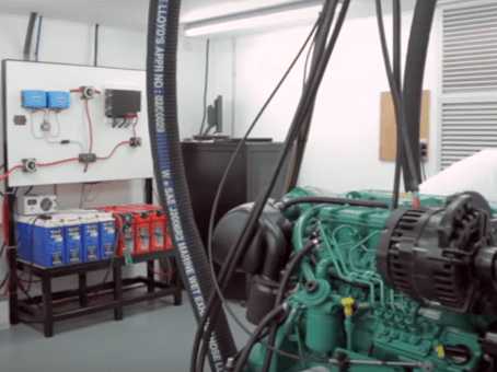
John Rushworth • 03 October 2018
Nigel Calder and the Integrel 9kW ‘Alternator on Steroids’
The screenshot above is that of world renowned yachting systems author Nigel Calder in the Triskel Marine lab with their new to market Integrel product, which makes some powerful claims – up to five to ten times the output of a conventional alternator. Integrel stands for Intelligent Generation of Electricity and as you can see – Victron products are part of the system. But what exactly is Integrel? Integrel gives high power outputs whilst cruising and at anchor when in standalone generator mode by using the spare power capacity available in a marine diesel cruising engine. This is achieved with the help of permanent magnets, intelligent loading and management of the system. As a product it is classed as ‘an advanced generator replacement technology’. The system was revealed at the recent Southampton boat show. Don’t worry if you missed it and want to see the system, there’s an on the water opportunity at METS. More of that later. Who needs a standalone generator… As a fellow sailor friend (MD of OceanTools ) said when I told him about Integrel: “I’ve been saying for years that a cruising yacht doesn’t need two engines.” Or as Nigel puts it: “This system is the one I’ve always wanted in my own boat for the last 35 years and now it has been finally achieved.” In fact he calls it – his retirement present to the cruising community – which over the years represents around ten million dollars in grant and R&D investment with both lab and on the water testing. By doing away with a separate generator, Triskel get typical standalone generator outputs using just Integrel. This has many benefits; for instance less space required, fewer through hulls, less expensive than an equivalent separate generator and as efficient as one, no extra separate generator running hours or maintenance. Having satisfied themselves of the reliability and efficiency of the system, Integrel is now available commercially and it looks like it may become the de facto standard for cruising yachts. Who needs a separate generator anyhow… Summary video Full technical video Specifications Victron Energy components such as inverter/chargers are offered as part of the standard and optional systems. Victron MPPT Solar Charge Controllers can also be added as an additional charging source. The standard Integrel system consists of: 9kW engine mounted Integrel generator Engine mounting kit Integrel system controller 48V battery sensor Integrel 600W 48V to 12/24/36V battery to battery charger 5″ touch screen user interface 48V 10kWh advanced lead acid battery bank Wiring loom and fuses 3kW 48V inverter/charger Additional options and upgrades: Additional battery storage can be added in 10kWh increments. Lithium ion batteries are available as an option Inverter/charger is also available in 5kW, 8kW, 10kW and 15kW Integrel battery to battery charger is upgradable in 600W increments to 2400W Simrad multi-function display Further battery sensors can be added to monitor the house and engine start batteries Integrel onboard Paul and Sheryl Shard of Distant Shores (a Sailing Adventure TV Series) features the Integrel system onboard their new Southerly 480 . Southerly are part of the Discovery Yachts Group . Conclusion Victron Energy are flattered that boating systems guru Nigel Calder and Triskel Marine are using our Inverter/Chargers as part of the Integrel system. If you want to see one of test boats with Integrel onboard, then a Hallberg-Rassy 42 will be on show in Amsterdam for the METS Show, from the 13th – 15th November 2018. This will enable people to see the Integrel system working in situ, on the water. The boat will be moored for the duration of the show at the City Marina and transport between METS and the marina will be laid on free-of-charge by Triskel. Those interested in finding out more about the system are encouraged to visit their stand at METS in Hall 7, Stand 033e, where you can chat and book a visit to the boat, or alternatively contact Triskel directly to reserve your slot . Of course Victron Energy will be at METS too, on stand 01.541 Interestingly Integrel has been entered for the 2018 DAME Awards for Machinery, Propulsion, Mechanical and Electrical Systems & Fittings, as well as entering two categories for the Boatbuilder Awards , including the Collaboration Category alongside Discovery Yachts. Results will be announced at the METS show and I suspect Integrel will be right up there – after all it does seem like a game changer for the cruising world. John Rushworth Links Nigel Calder’s books – https://www.waterstones.com/author/nigel-calder/104898 Integrel – https://www.integrelmarine.com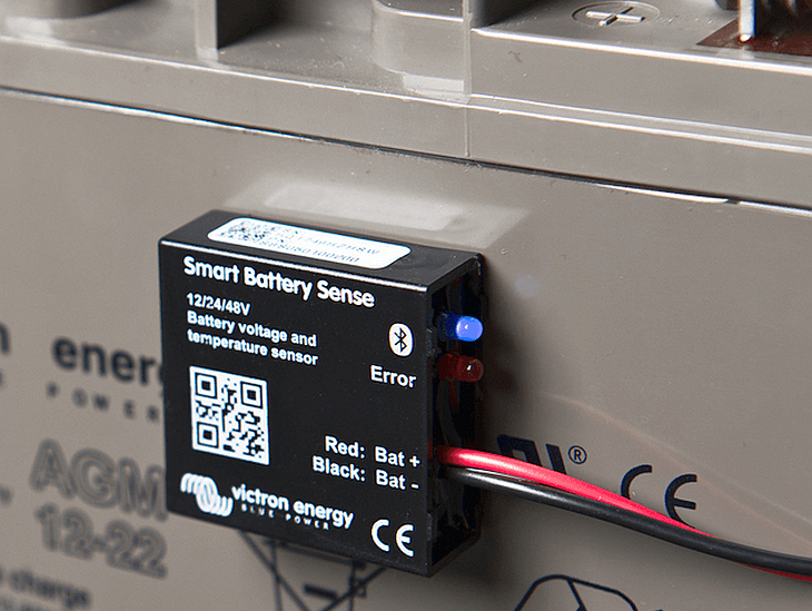
John Rushworth • 22 March 2018
Voltage & Temperature Sense for Solar Chargers
Our range of solar chargers fitted with a VE.Direct port were lacking battery voltage and temperature charge compensation. Not now ! Also, today we announce the launch of Victron Energy’s Smart Battery Sense – a product to complement the new feature. New, simple, smart …and wireless. Why do we need voltage and temperature sensing? Improves solar yield Maximises battery capacity Increases battery life AGM & Gel (lead acid) batteries use charging algorithms based on a standardised temperature of 25°C. However – when they’re cold these batteries need a higher charge-voltage …and a lower charge-voltage when they’re hot. So, optimally, we should modify the charge-voltage by, typically, -16.2mV/°C. Also there can be a difference between the voltage measured at an MPPT solar charger’s terminals, and that measured at the battery terminals. For optimum charging that discrepancy needs to be taken into account, too. The Victron Toolkit app demonstrates how this voltage drop is brought about as a consequence of cable length and gauge; together with voltage and current variations. Good news though: Our MPPT Solar Chargers and accessories can figure all this out – so you don’t have to! Voltage and Temperature data – transmitted wirelessly to your MPPT The Smart Battery Sense is a wireless battery voltage and temperature sensor for Victron MPPT Solar Chargers. Perfect partners. Simple installation – attach the unit to any battery by its self-adhesive tape. Protected by an inline fuse. Voltage and temperature data is transmitted wirelessly to the Solar Charger. Monitor & configure the unit from your smart phone – via our free-to-use VictronConnect app . Transmitted data can be networked to one, two – or more solar chargers connected to the same battery bank. Works for 12, 24 and 48 volt battery banks Works for both Lithium and Lead battery banks Compatible with most BlueSolar and SmartSolar MPPT charger models: see VE.Smart Networking for compatible-models list. Learn more from the Smart Battery Sense product page or from the Smart Battery Sense Manual – together with the VE.Smart Networking manual . Or watch the Smart Battery Sense introductory video: More options for Voltage- and Temperature- compensated charging Besides the Smart Battery Sense there are other options too. We’ve listed all of them in price order: Do nothing with no voltage-compensated charging. The MPPT already has ambient temperature sensing – though that method has its limitations. Installing Smart Battery Sense offers the best value for money. Connection to your solar charger(s) is wireless. Installing a BMV-712 Smart together with its temperature accessory , will provide full-blown battery monitoring, too. Connection to your solar charger(s) is wireless. Installing a Color Control GX or Venus GX , wired with a VE.Direct cable, and having DVCC enabled. This is for more complex systems – one’s which include inverter/chargers for example. Note: you may still need a BMV – subject to the battery-monitoring method for your system. Conclusion I’m pleased to see the launch of charge-compensated MPPTs; and of Smart Battery Sense . I’ll be happier knowing that my batteries are getting exactly the right charge with optimal temperature and voltage compensation. No matter how you choose to instigate voltage- and temperature- compensated charging, make sure you do – it brings only benefits! I always say: There are many ways to skin a cat – and the choice is yours. But Smart Battery Sense certainly does make sense when it comes to simplicity and economics! John Rushworth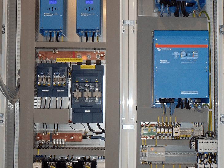
John Rushworth • 13 March 2018
Victron enhanced off-grid system
A guest blog by Victron Energy dealer Neosolar & Asolar, who are based in the Czech Republic. This off-grid system was designed with high reliability and innovative functionality in mind – using Victron Energy products to assist in achieving these goals. The system has proven itself operationally, having been originally commissioned on 12th February 2016. Unique design Czech companies Neosolar and Asolar implemented a unique off grid system for a family house in a permanently inhabited secluded newly built duplex. The building is not only a classic family house, but also the background for a small family farm. The main reason for building the system was the absence of a distribution network and high costs of its eventual construction. The investor’s requirement was straightforward: implement a sophisticated system with high operational reliability, low demands on operation and ease of use for all family members. It is a system with high operational reliability, minimum demands on operation and ease of use. It is a so-called DC-coupling with Victron MPPT solar controllers and hybrid Quattro and MultiPlus convertors and a lead-acid battery. The system is 230 V AC single-phase. Solar energy primarily powers appliances; the second priority is to recharge the battery, and the third is hot water. Main DC circuits of the PV off-grid system. Key: POLE PV1 PV1 SEGMENT MONITORING MONITORING MĚNIČ/NABÍJEČ CONVERTER/CHARGER OHŘEV TV HOT WATER HEATING KOTEL PELETKY PELLET BOILER DC OHŘEV DC HEATING AC OHŘEV AC HEATING ON/OFF DLE SOC ON/OFF ACCORDING TO SOC BATERIOVÝ MONITOR BATTERY MONITOR MANAŽER SOC SOC MANAGER PV segments and MPPT chargers The PV array consists of 36 pieces of polycrystalline panels with a total output of 9.9 kWp. It uses two Victron BlueSolar MPPT solar chargers 150 V/85 A. Their data link optimises common operations, but can also work independently. There is a possibility of their easy functional inactivation (DC-manual bypass) with direct connection to panels, and a battery with solar emergency battery charging without MPPT controllers for non-standard situations. Photovoltaic array of the island system consists of 36 modules with a total nominal output of 9.9 kWp. Concept of two independent converters Reliability is ensured by a pair of mutually independent converters. Main is the converter / charger Quattro 48 V DC/VA 10000/140-100/100 A. It is complemented by a converter/charger MultiPlus 48 V DC/5000 VA/70-100 A. That represents major converter when needed, and allows for reduction of operational energy during periods of low power consumption. Both converters can be output-united with a common power output of 13.5 kW in extraordinary consumptions. And that’s not all! The joint performance can be added to the main generator power of 5 kW (PowerAssist functionality). Permanent consumption can therefore be up to 18.5 kW. The “Select converter” option selector switch makes possible to manually select the converter (reduce operating power, fault), power their mutual affinity (increased consumptions), or shut down without the need for complicated parameterization. Single-line diagram of the “Select converter” switch; the building powered by the main converter. Key: PŘÍVOD EC EC SUPPLY HLAVNÍ MAIN ODVOD DŮM DISTRIBUTION HOUSE ZÁLOŽNÍ BACKUP Two generators – backup power security in every situation (concept of two independent sources) The main source of additional electricity is a single-phase generator with output power of 5 kW and automatic start controlled by the rate of battery discharge (lack of solar energy, protective charging of the battery). If necessary, there is a possibility of easy manual start by the switch regardless of the state of the system. The operation of the exchange is only allowed in the daytime to eliminate night time rush except in emergencies. The system is equipped with a backup generator with an output of 2 kW in case of failure of the main generator. It is started manually. Supplemental energy source is selected using the “Source selection” switch that allows you selection of the option “Off” – house wiring disconnected from both generators; options “Power by main generator” and “Backup generator power” are used for direct power supply of the house wiring from the generators in case the converter need to be disabled; options “Main generator + converter power” and “Backup generator + converter power” are standard options combining common functioning of the converter and the selected generator. Main generator Kipor IG 6000 Sinemaster including automatic start (switchboard) and possibility of connecting backup generator Kipor Sinemaster ID 2600 (black cable). Single-line diagram of the “Source selection ” switch. Key: VOLBA ZDROJE POWER SUPPLY SELECTION VOLBA MĚNIČC CONVERTER SELECTION EC1 – ZÁLOŽNÍ EC1 – BACKUP MANAŽER SOC SOC MANAGER POZICE PŘEPÍNAČE SA1 SA1 SELECTOR SWITCH POSITION 0 – NAPÁJENÍ DOMU VYPNUTO 0 – HOUSE POWER OFF 1 – ZÁLOŽNÍ CENTRÁLA EC1 (ZDROJ1) 1 – BACKUP EXCHANGE EC1 (SOURCE1) 2 – ZÁLOŽNÍ CENTRÁLA EC1 + MĚNIČ 2 – BACKUP EXCHANGE EC1 + CONVERTER 3 – HLAVNÍ CENTRÁLA EC2 (ZDROJ2) 3 – MAIN EXCHANGE EC2 (SOURCE2) 4 – HLAVNÍ CENTRÁLA EC2 + MĚNIČ 4 – MAIN EXCHANGE EC2 + CONVERTER POZICE PŘEPÍNAČE SA2 SA2 SELECTOR SWITCH POSITION 0 – OBA MĚNIČE ODPOJENY OD ROZVODŮ DOMU 0 – BOTH CONVERTERS DISCONNECTED FROM HOUSE WIRING 1 – DŮM NAPÁJEN MĚNIČEM INV2 (4,5kW) – ZÁLOŽNÍ MĚNIČ 1 – HOUSE POWERED BY CONVERTER INV2 (4.5kW) – BACKUP CONVERTER 2 – DŮM NAPÁJEN MĚNIČEM INV1 (9kW) – HLAVNÍ MĚNIČ 2 – HOUSE POWERED BY CONVERTER INV1 (9kW) – MAIN CONVERTER 3 – DŮM NAPÁJEN OBĚMA MĚNIČI INV1 A INV2 (9kW + 4,5kW) – POSÍLENÍ VÝKONU 3 – HOUSE POWERED BY BOTH CONVERTERS INV1 & INV2 (4.5kW) – POWER SUPPORT Energy storage Energy storage provides OPzS lead battery with a capacity of 1520 Ah/48 V with a total of 73 kWh of storable energy. Lead technology requires regular protective recharging to prevent battery degradation. SOC Manager in case when the battery is not sufficiently charged with solar energy for some time starts automatically forced charging from the generator. Energy is stored in lead traction batteries with a total capacity of 73 kWh. PowerGen function – maximum use of the generator The system has exploitative feature to maximize the run of the main generator. The run of the generator is costly regardless of the degree of its energy utilization. Primarily, the generator charges the battery. In the final charging phase the absorption capacity of the battery is limited, and at that moment the surplus energy produced is redirected to water heating. The function is selectable via switch. DC and AC water heating After powering AC appliances and battery charging, the surplus solar energy is used to heat hot water. A unique direct-current 60VDC solution is used – connecting a heater directly to the main DC battery bus. Switching DC heating is governed by the current state of battery charge calculated by BMV700. If the battery charge rate is greater than 95%, DC water heating activates. If the battery charge rate drops to 94%, the heating switches off. If the current production of energy is higher than the common consumption of the AC appliances and the heater, the battery is charged to full state. If the production is lower than the consumption, including water heating, the battery is briefly discharged to 94% charge followed by turning off the DC water heating. The system is equipped with a selector switch that allows permanent shutdown of the DC water heating, or conversely activation of the heating even at the expense of deep discharge of the battery. Regulation to constant SOC value . Sample regulation of HSW (hot service water) at a constant SOC value. The advantage of water heating by DC current is zero wearing of the Quattro converter / charger and maintaining the power capacity for other AC household appliances. There are no energy losses by energy conversion from DC to AC. DC water heating engages MPPT solar chargers that maximize solar gains. The planned expansion of the system by a wind power plant will allow conversion of the excess wind power also to water heating. The system is also equipped with supplemental AC water heating with a separate heating element. In case of lack of solar energy, a switch can be manually use to activate AC water heating at the power of 0.5 kW or 4 kW for heating part of the water volume. Energy is pumped through the converter from DC sources (PV array, battery) or from the main generator. Compact design The internal technology is housed in a compact electrical switchboard. Outside the cabinet there is all the above described control equipment + warning lights of the system operation for fast selection and controlling the functional status. The precondition for reliability is also the clear visualization of the operational status, and the ease of operation (the “Select source” and “Select converter” switches). The internal technology is housed in a compact electrical switchboard. Detailed project preparation – precondition of reliability and future repairability of the system. Credits This guest blog and images are courtesy of Neosolar and Asolar.
John Rushworth • 18 December 2017
DIY ingenuity: Hydro Power in the Austrian Alps
You could be forgiven for thinking Markus Pauritsch is a fireman in his day job. In fact he’s been an IT professional for the last fourteen years, working in their ten employee family business . In my experience IT types like to tinker in their spare time and Markus is no different. His DIY tinkering has led to an off-grid project which has inspired him to get more involved in renewable energy themes and hopefully expand their business into that area. If ingenuity is anything to go by he’s certainly moving toward that goal – and to my mind takes first prize when it comes to using Victron products in unusual ways. Now, what about those fire hoses? An explanation Let’s take a step back before we get to the test phase shown in the video above and the fully powered off-grid cabin. There was connector waterproofing and a lot more besides to be done before this gemütlich retreat could be enjoyed to the full. Gemütlich is a german word defined as having a feeling or atmosphere of warmth and friendliness – the classic cosy cottage – or in this case a log cabin in the forests of the Austrian Alps. Cosy off-grid cabin although there can be up to a metre or more of snow in winter – a good job there’s a full hot water system and log fire to keep it all toasty. Solar power. The sun angle is not optimal during winter but yield in the summer is okay. Access to the log cabin (even in summer) requires a 4 x 4 – and after that challenging drive why not relax in the cabin’s sauna. Summer tidiness and winter logs preparation. Austrian alps retreat Markus bought the cabin from his grandfather in 2008, who originally bought it from some lumberjacks in the 70s. Over the years it was fully electrified, being powered by a Jenbach stationary diesel engine attached to a 5kVA generator. Flowing water from a spring (with that water heated by bottled gas) provides for a fully functional bathroom. Besides the Jenbach generator, Markus built up a 12V uninterruptible battery power supply for radio, 4G internet (formerly Astra2Connect), SAT TV, charging mobiles and laptops, a water pump, and some lighting. Victron solar – and hydro power? To charge the UPS batteries Markus installed 700Wp of Victron Energy solar panels with a BlueSolar Charger MPPT 100/50 . Solar needs MPPTs… It was naturally at this point that Markus got to know Victron Energy products and in particular their MPPT solar charge controllers. See this blog for matching solar modules to MPPT charge controllers and how they work. That got him thinking. As Markus relates: “I was amazed, how the Victron MPPTs worked – which prompted the question – could I get some Watts out of my stream? Getting useable power from a water wheel became a very interesting possibility, but there was no information or knowledge available if anyone had done this with a Victron MPPT before. I thought I’d try and after some research I ordered a wind turbine generator (via Ebay) and a Pelton wheel water turbine. Wind turbine generator connected to a Pelton wheel water turbine. I decided not to go the scientific way and calculate whatever needed to be calculated, instead I decided to go the ‘suck it and see’ way. First I got some fire hose from a friend of mine, over 200m of it! From the point where I wanted to place the wheel (200m upstream) I measured, with the help of digital geo services, a fall height of 40m. Rule of thumb calculations, along with hose losses, indicated a pressure of 3 to 3.5 bar and the real world pressure tests proved to be pretty good as you can see. The fire hose supply and setting the discharge proved to be tricky though. You have to have a static large volume supply and head to keep the hose filled and maintain the pressure. A cut up plastic water container collector was the cheapest and most effective solution to feed the hose. It has not moved an inch for many months now, even with heavy rain. When the water is high in the stream it simply flows over the edges as you can see. After playing around with nozzle settings using washers, I got a stable water flow. After rectification of the 3 Phase AC coming out of the generator, I measured up to 135V DC with maximum water pressure applied to the Pelton wheel, with no electric load. Based on this I bought a BlueSolar Charger MPPT 150/35 and 2 big ripple capacitors of 160V 12,000 microfarads (μF) each. I did not test if they were needed or not as I just thought ‘hüfts nix schads nix’, which means if it doesn’t help it doesn’t make damage. In fact I think the caps are good for the Power Point Tracker circuit, as I would not like to receive much ripple voltage if I were a solar charge controller. Testing DC output after generator rectification. Capacitors used with the MPPT. Components boxed up and ready to go. Note 65A BatteryProtect bottom left. The results of this combination of components works great – with almost 200W continuous 12V charging power. Here’s the hydro generator in operation. I was very impressed once in full operation as you can see and hear how the MPPT works and searches for its power point when it is connected to the hydro generator. It works so smoothly and so fast, witnessed by the RPM being completely stable when the current draw is constant.” AC power, components and system monitoring To feed the AC loads Markus installed a MultiPlus inverter/charger (12/3000/120-16) . Conventional lighting was changed to LEDs, decreasing the power used from 700W to 170W whilst providing far more useable light. To monitor the battery a BMV-700 was installed. After thinking about how to monitor the Victron devices, Markus came across the Venus Raspberry Pi project. With the support of the super helpful Venus Dev Mailing list he got the Pi running with Venus and local touchscreen, thanks to Izak Burger and Jings. You can read more about Izak and his project in this blog post: Raspberry Pi running Victron’s Venus firmware . Raspberry Pi running Venus and local touch screen shown in demo mode. The Raspberry Pi with Venus and local touch display connects to Victron’s VRM via a 4G connection using a Huawai Modem/Router which is so stable and reliable, that it is just scary I’m told. It has been online 24/7 for months with no interruption. It has a Li-ion battery, so it is independent from the power source for a few hours in case of interruption. Markus certainly had some luck with local LTE coverage as the A2 motorway is but 2km away and LTE is supplied to the motorway – so he doesn’t even need external 4G antennas to connect to it. Previously he had Astra2Connect, but it was very expensive and the latency was particularly bad. Enhancements and the future It’s important to note this is not the final stage of the project, as the above is primarily proof of concept. For instance, a vacuum stable hose is far better for this application as it will get far more water flow in comparison to a firehose, and as a result more Watts out. However that is also a matter of cost as a vacuum stable, freeze capable, 80mm hose is around 4 to 5 Euro per metre – and with 230m required you can get a firehose by comparison very cheaply, as they get sorted out and retired by the fire departments after a time. Decisions, decisions. Here’s some future enhancements that Markus has planned: Use a better, vacuum stable hose. Improved ‘dirt management’ at the water feed barrel as leaves and small stones are problematic. Improved housing for the Pelton wheel and ‘wind’ generator. Improved cable management. Generator integration or maybe the Jenbach needs to retire as a standby solution, after a period of over 60 years of good service! Dashboard for Touch VenusPi and BMV and much more… Conclusion This hydro power solution all works beautifully, using ingenuity to keep the costs down and prove that BlueSolar Charger MPPTs can equally be called BlueHydro Charger MPPTs! My thanks go to Markus Pauritsch for the information and images used in this blog – we salute his ingenuity and passion for getting his project up and running. If you have any questions for him do leave a comment in Disqus below. I hope this pre festive season blog seeds ideas of how you might use Victron Energy products in 2018. In the meantime we wish you a fun and festive holiday. John Rushworth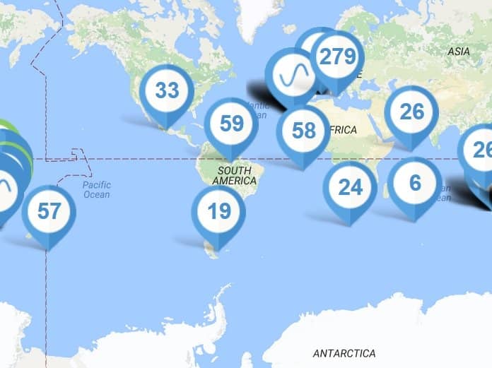
Matthijs Vader • 25 May 2017
Lessons learned: Thrusters, Lithium and SOC
Good day, Calling all dealers, designers and installers. Recently I’ve been involved in two technical support cases of which I want to share my insights and the lessons learned. The first is about Battery State of Charge, and especially for systems that include a Color Control GX or Venus GX. The various options can be quite confusing and initially we didn’t have a manual explaining them. We do now! See the SOC link below. Please take the time to study this carefully. Anyone involved with advising, designing or troubleshooting systems with the aforementioned devices should know this by heart: Battery State of Charge (SOC) The second lesson concerns a typical marine topic: bow and/or stern thrusters and their batteries. The conclusion is simple: don’t put thrusters on the house battery, especially don’t do so when using bms protected lithium for the house battery. The main reasons for that: Combining thrusters on one battery with Multis and other electronics is not a good idea: spikes from thrusters cause issues and/or damage to the connected electronics. Another reason why combining thrusters with house loads is not a good idea: using the thruster can empty the battery of the whole boat, instead of only its own battery. Having thrusters on a lithium battery with a BMS that will disconnect them in case of any issue is not a good idea either: just imagine a sudden cut out in the middle of a manoeuvre without pre-warning. Note that we do not give warranty on our batteries if there is no BMS with full disconnect installed, which basically rules out Victron lithium batteries for such purpose. Instead opt for a simple separate battery, without a disconnect BMS. Then the helmsman will automatically be warned when the battery is at a low SOC: in that you’ll feel that the thrusters are losing power, rather than having to do without them, without any pre-warning. So please make sure not to advise nor accept such installations as a designer, dealer or installer. Have a good weekend! Matthijs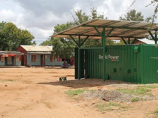
Matthijs Vader • 01 December 2016
Building an unattended battery based energy system
Good day! Lately, I have been involved in several unattended Victron systems. Some of these being large scale containerised systems, such as the one shown above. And now that I think of it; as a system designer or installer you could consider almost all systems as unattended, as there will rarely be a trained Victron technician/installer onsite all of the time. In that case and in this post I’ll highlight several ideas that I have either seen or that have come to mind whilst helping to make such systems robust and foolproof. Add a manual bypass switch Install a large manual bypass switch, which connects the AC input directly to the loads. This will prove invaluable in case the Multis or Quattros need a configuration change, or on occasion some other maintenance. Mount a changeover switch to easily swap phases on the AC-in A three-phase setup that moves around as a container based system, for example from outdoor event to outdoor event, will have different loads as well as a different genset and mains supply at every event. It’s likely in that case that there will be a genset connected at some point with incorrectly wired phase rotation. As a result of that the Multis or Quattros will reject the input and stay in inverter mode, consequently draining the batteries. The solution is to take a set of screwdrivers and rewire the three-phase plug on the genset, but that costs time and perhaps even a mandatory discussion with the genset supplier. Mounting a simple changeover switch that can swap two of the phases is a nice solution which instantly fixes the phase-rotation issue, without stalling the event. Besides manual switching there are also automatic devices available to do this. Mount some simple analog volt meters When it comes to monitoring, mount simple analogue volt meters on the input as the Color Control GX will not show input voltages when AC input is either ignored or not accepted because of phase rotation. For more basic information of how to wire and configure a larger Victron system, see our manual on parallel and three phase systems . Which battery technology to use? Lithium? GEL or AGM? OPzS? That is really up to you. Some issues that might help in the decision process: How often will the battery be cycled? If say once a week, then 52 cycles a year. For such a low cycle use case, don’t be so sure that a Lithium pack is worth the investment. However, when cycled every day, it could well be that Lithium is worth the investment. Beware of the capital cost risk though; even with all the security and BMS-es it is quite easy to destroy a lithium battery pack. Damaging a lower cost lead-acid based battery bank is less of a disaster. An earlier blog discusses the various merits of two battery types: Lithium-ion vs AGM . When using lead acid batteries, consider adding our battery balancers to enhance the lifetime of the pack. And wire an alarm lamp or something else that is really obvious to users thereby ensuring a faulty battery is noticed in time – before it causes the whole bank to get damaged. For large battery banks, work with large 2V cells in series. Combining lots of 12V batteries in parallel and in series is a recipe for disaster. Add a battery monitor BMV 700 series and Color Color GX shown in centre of photo, along with appropriate plugs, sockets and RCDs/Breakers; all fitted behind a secured panel on the side of the container. Install a Battery Monitor, like the BMV-700 series . It will keep a record of essential historical parameters, like minimum battery voltage ever seen, max battery voltage ever seen, total energy used to charge, total energy discharged from the battery and other useful information. This will help in evaluating what has happened to the battery and its ‘state of life’. Of course in an AC only setup you could use the built-in battery monitor of the Multi, but that will (A) be less accurate and (B) will not have a list of historical parameters. Powering the communications equipment Take extra care that the Color Control GX and any mobile broadband router and/or other communications equipment does not power down when the VE.Bus system is switched off. Use for example a separate small inverter to power them or power them straight from the battery. Ensure reliable internet connectivity Install a Color Control GX connected to the internet, so you can track the system remotely on our VRM Portal and even remotely change the system configuration. The advice: Use wired Ethernet, and not WiFi Use wired Ethernet (a RJ45 LAN cable) for communication between the internet router and CCGX. Don’t use Wi-Fi. Although fine in a house, Wi-Fi is not meant for an unattended setup. Think about it, have you ever seen computer servers with Wi-Fi cards in a data centre? (image is courtesy of Cory Crow ) Instead, all servers in a data centre each have at least two (!) Ethernet connections to the rest of the system. Several customer cases have already shown that Wi-Fi is not reliable enough for an unattended setup in a mission critical installation. Use a professional 3G router In case of a cellular as opposed to a fixed internet connection, use a 3G (or 2.5G, 4G) router that is designed for unattended setups. Do not use a consumer mobile routers, intended for business or leisure travel. The more expensive professional router will quickly pay for itself and won’t require you to travel up and down to site, only to find out that all it needed was a power cycle. Examples of such professional routers are the H685 4G LTE from Proroute, as well as the Industrial 4G router range from Pepwave . Note that these are just two which have been recommended to me by customers. I have not tried them myself. There are many more out there, so please post your experiences below or on this off-grid monitoring blog-post , which is all about 3G and 4G routers. And, use ethernet to connect the 3G router to the CCGX. Do not use Wi-Fi for this. Color Control configuration Disable auto updates on the CCGX: there is no need to update a running and well working system. Do make a habit of regularly updating it when you have time and are around a bit longer to make sure all still works 100%. Enable full remote access (note that this does increase internet data usage!): Enable Remote Console for VRM / Internet. Enable Two way communication: remotely change the configuration of the Multis or Quattros. Enable Remote Support: allows login by a Victron engineer in case of problems that can’t be solved in another way. Insert a microSD card into the CCGX Ensure that you install a microSD card in the CCGX. This allows the CCGX to save readings for longer than 48 hours if the internet connection is down or of poor quality. More details here in the CCGX manual . Automatic generator start/stop Use the highly configurable genset start/stop functionality on the CCGX . Sound the alarm in case the genset can’t start: Besides just making the genset start, also configure the BMV to close its relay in case the Battery Voltage or SOC drops below the thresholds that should have triggered a genset start. And wire a siren or otherwise very visible or audible alarm to that relay. And train the people close to the container to watch out for that. Prevent unwanted changes of parameters Lock the CCGX to the User access level Lock the BMV setup menu More ideas? I know that there are thousands of similar Victron setups out there, all over the world. Please post and share your ideas and recommendations below, making this a very complete handbook for unattended setups. Best regards, Matthijs Vader Credits Headline image courtesy of E.ON Off Grid Solutions GmbH , trading under the brand name Rafiki Power and operating as a service provider for off-grid energy solutions in East Africa, with offices in Düsseldorf and Arusha (Tanzania).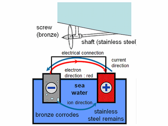
John Rushworth • 10 October 2016
Protect your boat from galvanic corrosion
Here is a short guest blog from Victron Energy distributor Energy Solutions, which I hope fellow sailors will find useful. In fact, when I was looking for a galvanic corrosion solution for my own boat I didn’t even realise Victron Energy made them! And on that note if you want a quick way to see the full range of Victron products, at a glance, I find the pricelist with images in it very handy: https://www.victronenergy.com/information/pricelist Thanks to Melanie Lay of Energy Solutions for sending me the information used in this blog. John Rushworth Galvanic corrosion Galvanic corrosion is the process that can cause the hull of your boat to start to corrode when you are connected to shore power. Corrosion occurs when two dissimilar metals are immersed in a conductive solution (sea water) and are electrically connected (by the shore connection). One metal is protected, whilst the other is corroded i.e. your boat’s hull. This is the same type of corrosion that occurs in a battery to release energy. This type of corrosion can cause an electrical current to run from your boat’s hull to the shoreline; which could potentially electrocute a swimmer swimming between your boat and the shore when you are connected to the shore power. It is essential you protect your boat and the swimmers in the water from this risk. There is a common misconception that galvanic corrosion can only occur in metal or aluminium hulls but in fact, it can occur in any boat that has metal in contact with the water such as the propeller and shaft, skin fittings etc. Solutions There are two ways to protect from galvanic corrosion; either by installing an isolation transformer or a galvanic isolator. An isolation transformer eliminates any electrical continuity between shore power and the boat. The shore power is fed to the primary side of the transformer and the ship is connected to the secondary. The isolation transformer completely isolates the boat from the shore ground. By connecting all metal parts to the neutral output on the secondary side of the transformer, in the case of a short circuit a circuit breaker will trip or a fuse will blow. Another option is to install a galvanic isolator , this consists of two internal diodes which are connected in anti-parallel. When they are connected in this way, the diodes allow current in both directions but only above a certain threshold voltage. The isolator is installed directly behind your boat’s 230V connection. The forward voltage from the galvanic isolator is higher than the potential difference between metals. As a result, this voltage will not allow conduction and as such, the galvanic isolator will prevent any electrolytic current. However, if there is a (higher) error voltage in the AC circuit, the diodes will allow current through and the residual-current device will break the circuit. Energy Solutions Website: http://energy-solutions.co.uk ES Online Store: http://www.es-store.co.uk Facebook: https://www.facebook.com/EnergySolutionsUK
Matthijs Vader • 05 September 2016
Configuring solar systems with Quattros and Multis
Good day! To help determine which settings are the most suitable for different types of solar systems using a Victron Energy Quattro or MultiPlus Inverter/Charger, we have developed a guide: VE.Bus-solar-system-configs (an Excel *.xlsx file). There is also identical content in this PDF guide , for those that don’t have Excel. This guide is a decision tree that will help installers discuss system installations with their customers. By choosing one answer that best reflects a system (for each of four questions asked) a recommended software configuration will be arrived at. Here are the details of those four questions: Q 1: What type of system? A backup system: the (only) goal of the energy stored in the battery is to power the loads during a mains outage. A pure self-consumption system: all energy stored in the battery can be used to power the loads when there is no, or not enough solar power available. A self-consumption system with a battery reserve: a mix of the two types above. For example use the top 30% of the battery to increase the self-use of solar power, whilst keeping the other 70% available for a mains outage. Off-grid site: no mains available. Only a genset, or not even that. Intentional islanding: used in countries with a bad grid. For example with brown outs and spikes. In this case it is preferred to always run in Inverter mode, even when the public grid is available. The well known corresponding setting is AC Ignore in VEConfigure3. Q 2: How to charge the batteries? Always: typically for a backup system: when the power is restored, the customer wants to have the battery recharged as fast as possible, which includes recharging the battery with power from the grid. PV Only: use only power coming from the sun to charge the batteries, except when the lifetime of the battery is at stake. For example, a prolonged shortage due to bad weather. In that case Sustain will use a minimal amount of energy from the grid to keep the batteries in a healthy state. Genset. Q 3: Is feed-in allowed? This is an important and changing political topic in many countries. In Spain there is even a tax on energy harvested from the sun, for systems that are totally off-grid! Politics aside for now, the different answers we have seen are: Feed-in is wanted: the meter runs in reverse, or there is some other mechanism in place that lets the customer sell energy back to the utility. Feed-in is no problem, but not wanted either: all energy being fed back is lost, in a sense that it is not being payed for by the utility. But it doesn’t hurt either. Feed-in is absolutely not wanted, not even for a few seconds: to illustrate, there are certain prepaid meters in South-Africa that will disconnect the customer when it detects energy being fed back into the grid. Feed-in is not wanted, because every kWh being fed back is just counted as energy being used and feeding back increases the end-customer’s energy bill instead of decreasing it. Q 4: PV Inverters or MPPT Solar Charge Controllers? If PV Inverters, look for the lines in the Excel sheet that state AC-Coupled. If MPPT Solar Charge controllers, look for the lines in the guide that state DC-Coupled. Configuration solution Having answered the four questions together with the user of the system, look in the guide to see where the decision tree guides you. Hub-4 for a system containing only MPPTs? One thing you’ll find when examining the guide is that the Hub-4 Assistant shows up in many places, even in systems with MPPT Charge Controllers. This solution has several advantages over the other Assistants. To name but a few: There is an extensive manual for the Hub-4 system . Set SOC levels: the Hub-1 Assistant can not work with SOC levels, it works on voltage. BatteryLife : prevent cycling your batteries at their low end. Use the grid when available: no switching between grid and inverter, less risk of overload, sinus wave distortions and other issues. See the last question in the Hub-4 FAQ for more details on making a DC-Coupled system with the Hub-4 Assistant. Conclusion I am convinced this guide will help you find the right approach in designing systems for your customers. It has certainly helped me recently when guiding dealers and distributors, as well as end-customers. We’ll be improving the guide and further simplifying the software setup as we move along, which will help us come closer and closer to our end-goal: setting up a system should be simple and intuitive. In case of any questions, please use the Disqus comments section below. Best regards, Matthijs
John Rushworth • 29 August 2016
MultiPlus magic: Small generator, big power
Have you ever tried to explain to an end user or friend what a Victron Energy MultiPlus is? When that happened to me, it was quite some time before I realised the true value and capabilities of one integrated product that combines both a battery charger and inverter – a product I may add that is far more than the sum of it’s parts. Up to that point I had simply assumed I would add a separate charger and inverter to my sailing yacht as funds and needs dictated. How wrong I was. Of course the same can be true for other off-grid/sometimes grid connected situations. It might be a campervan, motorhome, RV, canal barge, Tiny house or a cabin in the woods. Victron and RV aficionados Chris & Cherie of Technomadia describe the MultiPlus best I think, calling it a ‘Hybrid Inverter’. In fact they have produced some excellent videos about their own projects which describe the Multiplus well, and how they use it. More about that later. First a bit about how I came to integrate a MultiPlus into my boat and what I mainly use it for, including using it as a short term electric propulsion booster or range extender. If that depth of reading detailed below is not your particular interest, then maybe skip to the videos at the end of this blog for a quicker insight into Multiplus magic. End user choices I’m initially a retail customer that chose to use Victron products long before I started maintaining this blog. That choice was because Victron had a complete range of the products I needed (along with good online technical information and support) without having to go to multiple suppliers. I also liked the idea that their products integrated and I could easily add/combine them as my personal boat project progressed and funds permitted. A modular, progressive build. First a bit about that, then more about my favourite components: the MultiPlus and Color Control GX combined with the terrific performance of Lithium Ion batteries . Then and now What started off as a few large AGM batteries at 24V, a charger, a battery monitor and a DC-DC converter (for 12V house loads) when converting my sailing yacht to electric propulsion – has over the last five years expanded into a comprehensive solution. Here’s a photo of the old diesel engine space as it is now. There’s a lot of Victron blue. The photo shows 2 x 12.8V 200 Ah Lithium-iron-phosphate (LiFePO4 or LFP) propulsion batteries with cell balancing and BMS (shown centre). From front to back, starting on the left – Cyrix load & charge under/over voltage cut off relays, 200 Amp main fuse. Top left 1 x 10A and 1 x 6 A 230V shore power breaker with galvanic isolator (I didn’t realise Victron made a galvanic isolator when I bought that), then the PWM electric motor controller box with a BMV-702 shunt fitted inside and a 600 Watt Phoenix charger (for the LFPs) behind that. Right from front – 12 A extra charger for the 24V x 130 Ah AGM house bank, 16 A extra charger for Lithium propulsion bank, 75/15 MPPT Solar Charger Controller to run my 4G router which accesses the Victron VRM site, a 50Watt tube heater (behind the auto fire extinguisher) to keep moisture at bay in the propulsion space. Out of sight, behind the batteries, is the L.M.C/Lynch electric motor , controller and propulsion drive train. The project is all my own work. Not too bad I hope for an ex Royal Navy steam engineer who is mostly mystified by electrics and electronics. More power needed As I got use to my original basic system I realised I needed more battery power for house loads (a small fridge for cold beer to be precise) rather than tapping off the propulsion bank using a DC-DC converter. Space as you can see is limited but fortunately I had other space under the port and starboard bunks where the old diesel flooded lead acid starter battery and house battery use to be. To keep voltage drops and wire sizes to a minimum I decided to go 24V. My house loads system now comprises; 2 x 130 Ah AGMs in series fitted with BMV-702 temperature monitoring probe 1 x Compact 24V/ 800Watt/16Amp Multiplus 1 x BMV-702 1 x Color Control GX (which also monitors the LFP propulsion bank as well as the house bank) 1 x Orion 24/12 40 Amp DC-DC converter for house loads 2 x 30 Watt Victron solar panels (shown in headline image) to help run my 4G router 24/7 1 x 75/15 MPPT solar charge controller To bring the charge rate of the house bank up to around 0.2 C of it’s 130Ah capacity (130 x 0.2 =26 Amps) I added a Blue Power 24V/12A IP67 Battery Charger which when added to the 16 Amps of the Multiplus gave me a combined and decent charge rate of 28 Amps for the house bank, without going to the expense of a larger Multiplus than the 800 Watts output (700 Watts continuous @ 25C) I chose. This also gave me the added bonus of charger redundancy and choices for slower and faster charging. Why a small MultiPlus? Simple really, space and finances. However there is a little more to it than that. Whilst the former is true and that limited the size of the Multi and the batteries, I simply didn’t need the inverter side to be more than 800 Watts. That size also complimented the 130 Ah rating of the batteries. Keeping the ‘shrinkage’ of AGM batteries to a minimum when considering Peukert’s law is always a good idea when using an inverter for short term higher loads. I also prefer these kind of batteries in series rather than parallel for safety, not to mention that running the bank at 24V rather than 12V keeps wiring sizes smaller. For continuous house loads it is always a good idea to have the loads equal to or smaller than the 20 hour rating of the battery. In my case the continuous loads when sailing are usually no more than 4 Amps (4 x 12=48 Watts). At 24V that’s only 2 Amps being drawn from the house battery. As the 20 hr rating of the 130’s is 130 x 0.05= 6.5 Amps, I have a genuine 130 Ah bank rather than any reduction/shrinkage in Ah due to Peukert. Inverter appliances As mentioned above there were good reasons for choosing a smaller Multi, but what about the type of appliances you might run from an inverter? Some might be long term loads such as a laptop running on an AC supply. That of course does not present a problem as a laptop might only be 45 Watts. But what if you want to run a kettle for example, a larger short term load. My solution was simply to specify the appliances based on inverter size rather than have a larger inverter for typical larger sized home appliances, which would not be good for a small house bank anyhow. The ‘higher’ loads and appliances I run from and via my 800 Watt Multi are: 600 Watt travel kettle 750 Watt toaster 700 Watt George Foreman type grill Of course this means you can only run one appliance at a time – or does it? Also the AC output of the Multi can supply: 30 Watt electric blanket (it gets cold in Scotland!) 45 Watt Laptop supply 288 Watt (12 Amp) Blue Power 24V/12A IP67 (House) Charger 384 Watt (16 Amp) Blue Power IP22 (Propulsion) Charger 600 Watt (24 Amp) Phoenix (Propulsion) Charger Why on earth would you want to charge or supply the LFP bank using the two propulsion chargers from the MultiPlus house bank batteries you may wonder, by using the inverter side of the Multi? Yes, it would be inefficient but there’s a very good reason. What about the desire to have coffee and toast at the same time, which exceeds the MultiPlus inverter rating? All the above can be done with the magic of the MultiPlus and a small generator. MultiPlus magic Onboard, as shown in the headline image, I have a small Honda Generator of the silent or suitcase type. It is a 1 kVA or rather 900 Watts continuous. Honda also do a 2kVA which uses the same 50 cc engine running at a higher (noisier) speed and output. The continuous output is 1,600 Watts and as it costs 50% more than the smaller one it made sense to me to choose the latter. That’s not only because of value for money but also because I only ever have short term requirements for higher loads. There’s no point in running a larger generator if it’s not loaded to capacity, as that is inefficient. Let’s say I’m anchored and have been away for a few days and want to put some charge into my propulsion LFP bank using the Phoenix and IP 22 Charger, which combined can supply 984 Watts or more (1,100 Watts in fact in bulk) to the Lithiums. I can also adjust to a range of charge currents with the Phoenix Charger Control shown below. If I run the generator there is 900 Watts available to the Multiplus for a combination of charging the house bank from the Multi’s inbuilt 16 Amp charger (384 Watts) and/or using any of the AC appliances stated previously. So, I run the generator and it’s partially loaded by the 384 Watt inbuilt charger and 16 Amps is going into the AGM house bank in bulk charge. Clearly that leaves me power to use. But it’s the LFP bank I want to charge and not the house bank. Switching on both the LFP chargers and by adjusting the Phoenix Charger Control I can set the LFPs to use the full 900 Watts of the generator, at which point the Multi reduces it’s charge current to nil to the house bank, if the Multi’s main switch is in the ‘On’ position (inverter available) and the charge current limit is set in the Multi to 4 Amps using the Color Control. This stops overloading the generator (230V x 4 = 920 Watts). See this blog about that new overview screen . But now I want coffee and toast and still to put some charge into the propulsion LFP bank. Coffee and toast will cost me a total of 1,350 Watts, but I’m already using the full 900 of the generator. What to do, as all that totalled up is 2,450 Watts. Clearly sacrifices have to be made. I switch off the Phoenix leaving the IP 22 Lithium charger on at 384 Watts. The generator load has decreased from the full 900 Watts and now the Multi is charging the house bank too and the LFP bank (384 + 384 = 768 Watts). Time for coffee, which will exceed the 900 Watts the generator can supply (768 + 600 = 1,368 Watts). When I switch on the 600 Watt kettle a seamless fast transfer switch built into the Multi kicks in and the house bank starts discharging to supply the inverter to add to the generator power. A maximum of 900 Watts from the generator plus 700 Watts (continuous) equalling 1,600 Watts is therefore available, by combining the small generator and the Multiplus. Small generator, big power. The moral of all this is to size your generator to take care of longer term loads, which allows you to fully load the generator for efficiency. And when short term higher loads are required – simply use an appropriately sized battery bank and Multiplus which gives the additive power of a generator and the inverter part of the Multiplus. That’s Multiplus magic. MultiPlus with a Color Control GX These two products really are perfect partners and they allow me total control and monitoring in a way I only dreamt of a few years back. Say I’ve returned from a weekend away sailing and both my house and propulsion banks are quite depleted. Plugging into the marina 230V/16A shore supply; all my chargers go on. Around 1,100 Watts to the propulsion bank and around 700 Watts to the house bank, run from a 10 Amp/230V breaker supply via the Multiplus and a bank of AC sockets . The Multiplus and chargers are using a total of 1,800 Watts leaving around 500 Watts spare. As this is a Multiplus there’s still room to boil that 600 Watt kettle, make a toasted sandwich and plug the laptop in! That’s the beauty of the ‘Power Assist’ feature of the Multi. To allow that I simply set the current limit in the Color Control to 10 Amps so that the 10 Amp breaker supply will not get exceeded and trip that breaker. That all leaves a separate 6A breaker and sockets for a straight AC supply of around 1,380 Watts for a small fan heater and/or power tools. Quite often by the time I’ve done some chores the propulsion bank is fully charged and the house bank is still labouring in absorption charge. That is one of the joys of Lithiums; fast charging to around 98%, whereas the house bank will have slowed it’s charge rate down at around 80% SOC and gone from bulk to absorption. There will be quite some time that will need to elapse before float and storage are reached; one of the downsides of lead acid technology such as AGM. Not so with Lithiums as they charge fully quickly and/or they can be left in pretty much in any state of charge. However with a Multiplus, Color Control GX and an internet connection there is simply no need to concern oneself about battery SOCs, as you can leave the boat at any point and control the system remotely via a Smartphone or Laptop. This is called ‘Remote Console’. To achieve that I have a D-Link DWR-921 4G LTE router as shown below, which ensures 24/7 connectivity and data logging via the VRM. It runs from a 12V DC supply, rather than the 230V supplied transformer. Tips & tricks As the Lithiums are often fully charged by the time I leave the boat (having taken them from 98% to 100% for around an hour which ensures cell balancing) I simply switch off the BMS as the Cyrix load relay takes a few Watts and would discharge the bank a little before the next sail. I have also wired the BMV-702 & Shunt on the load side of the load relay. This means there is always a very slight current to keep the relay closed, meaning the power is always available for electric propulsion when the electric motor ignition key/solenoid is switched on. On an electric propulsion boat you always want power there immediately and not have to wait 30 seconds for a Cyrix relay to close! The bank is still protected and monitored for temperature, under voltage/over discharge and over voltage/over charge. The extra connection on the BMV-702 (as opposed to the BMV-700 which doesn’t have one) is used for temperature monitoring, rather than for a non existent starter battery or Battery Balancer that you may choose to use in a conventional system. A VRM Remote Console (via a laptop rather than the App) screenshot is shown below with the temperature of the Lithiums as I write. You’ll also notice in the top right, next to the time, a symbol. This shows that a GPS dongle is connected to the Color Control, which apart from logging your tracks can be set with a Geofence and an email alarm – just in case some opportunist decides to steal your pride and joy. If I were leaving the batteries over winter layup for many months, I’d probably leave the Lithiums at around 60% SOC. During the season though I like to have them fully charged and ready for use. You never know when the wind will blow and the sun will shine! The Multiplus has 3 switch positions on it’s front panel. By leaving the switch in the On position all control can be done directly from a Color Control GX: MultiPlus On – The charger is on and the inverter is available subject to the current limit set either via a Digital Multi Control or the Color Control. The image below shows my house batteries in ‘Storage’ and the current limit set to 10 Amps. There is a downside to this though if leaving the boat unattended. If the shore supply fails and say I had my engine space AC 60 Watt tube heater on, the inverter will kick in and over time deplete the house bank. Of course you can set email alarms to warn you of this or fit a Battery Protect to disconnect the house bank. Multiplus Off – Exactly what it says, shown in the screenshot below showing the primary Overview screen. Charger and Inverter and AC sockets are all off. Now my 2 x 30 Watt Victron solar panels in series with the 75/15 MPPT is enough, during the Summer months, to maintain the house batteries in a good state of charge with the 24/7, 8 Watts that the router takes to keep the system connected to the VRM. Here’s an alternative Overview screen shown below which gives similar information to that above plus access to Current limit settings and other information. Note the GPS speed readout in Knots. It can be set for other speed units too. MultiPlus Charger Only – I use this a lot in the marina and set the current limit to zero which stops the charger and inverter side and gives Passthru to the AC sockets. That way if the tube heater is on it will work if the shore supply is on and obviously not deplete the batteries (by using the inverter) were the shore supply to fail. Below is an example of a very good solar day. The 2 x 30 Watt panels are laid flat (see headline blog image) and in this instance I’ve harvested 320 Watts over a 24 hr period. That’s over over 5 times the panel rating harvested at 56 degrees latitude. Even the peak output exceeds the panel rating, 60 v 68 Watts. Average stored battery energy over the Summer months of May, June July usually works out at 2.5 times the panel/s rating in the UK. That of course is for a flat panel, as boats naturally move about and having an x and y axis tracker is not that beneficial in Summer, as it may only give me about 10% more harvest. Remote console via the VRM (used to get the screenshots above) is a great tool to control and monitor systems and of course there is always the option to store data locally if you are without an internet connection for your Color Control. Sure you won’t have Remote Console and other tools, but if all you want to do is see historical data after having uploaded it to the free VRM site, then no internet connection is required. Personally I wouldn’t want to be without a Remote Console connection when away from the boat. Obviously an internet connection is not such an issue when at sea, as data is stored on the Color Control internal drive or by using an inserted MicroSD card for larger offline data amounts. As soon as the boat is back within a 4G area the backlog data automatically uploads. To learn more about the Color Control & VRM, see Victron Live and why not create an account at Victron Professional: https://www.victronenergy.com/live/ https://professional.victronenergy.com/ Silent range extender One last scenario. The propulsion bank is nearly empty at sea but there’s still quite a bit left in the house bank and the generator is broken. I’ve sailed almost back to port but still need propulsion power for those last few miles. With the Multi on I can switch on the Lithium propulsion chargers; the house bank using the inverter side of the Multi will supply those chargers and therefore a short term electric propulsion boost to the empty Lithium batteries. Inefficient that might be, but to me that’s all good built in system redundancy using off the shelf products to provide a silent range extender in the event of generator failure for yacht Elektra. Of course if the generator is working then I can simply use the propulsion chargers and the full output of the generator (900 Watts) to run as a range extended battery electric boat, as opposed to a pure battery electric boat. This is my backup at sea and 5 litres of petrol is enough for 10 hours of motoring in calm waters, at around 3 to 3.5 knots. Of course the whole idea of electric propulsion is to do without any internal combustion engine, hence I invariably recharge at marinas and keep my generator as a backup for those times when a marina is not nearby. What about other users other than the marine world; such as full time RV’ers? More MultiPlus magic Earlier I mentioned RV aficionados Chris & Cherie of Technomadia and some excellent videos they have produced about their own RV, which describe the Multiplus well and how they use it. Big RV: Small Generator – Downsizing to a 2500w Propane Generator Flexible RV Electrical Systems – Running an AC Off Battery, Solar & Hybrid Inverter Conclusion If you have a story about how you’ve used Victron Energy products do let us know. Thanks to Chris & Cherie of Technomadia for letting me use their videos in this blog. John Rushworth
John Rushworth • 11 January 2016
Boat electrical installations: combating seawater
Introduction In his last article, Josip Zdenković, a Director of SCHRACK TECHNIK Ltd in Croatia, wrote a blog on the use of Victron Energy equipment on board the vessel Matsko. Josip and his team showed precisely how a ‘surgical incision’ could be done in the vessel’s electrical installation to add a quiet power source for times when the noise of generators is undesirable. He promised to describe at least some basic and general rules about the on-board installation in a further article. Here then, in Josip’s own words, is that article. This time assistance was provided by Dalibor Buljan, also from SCHRACK TECHNIK, in producing the pictures. Here is the previous article . Some details of boat installations This article is intended as an initial framework for your own research if you decide to self-build or reconstruct your vessel installation. We cannot say everything we want and be sure we have explained all to everyone in a sufficiently clear and precise manner! Do not forget, the people who will use your installation on board are far away from professionals and probably don’t have any special knowledge of using a vessel electrical installation. After studying this article, please consult a certified designer or company that deals with on-board installations daily and has suitably skilled workers. Reading this article does not enable you to work independently without further expert consultation. But perhaps it makes some things a little bit clearer than before… After we tie our boat at the marina or dock, the first thing we want to do is to connect the shore power. Our batteries are probably empty and we have already turned off the refrigerator to save battery power. Ultimately we want to connect to the stronger loads that are not used or needed during navigation. Figure 1 shows boats connected to electrical distributors with terminal box cabinets. Figure 1 – Dock on Vis Island is equipped with power terminal boxes designed by SCHRACK TECHNIK (same picture as headline image above but taken in summer) If we want to understand the on-board installation, let’s consider as the first step what we expect to find in the terminal box on shore, according to the standards for low voltage electrical installations, IEC 60364 Part 7-709, describing the requirements for installations in marinas and similar locations. To keep it simple: what kind of protection is expected when using power from the shore socket on the terminal box? Why should all this protection be used? The effects of current on a human The most important factor in the effect of electricity on a human is the current strength flowing through the human body, as follows: releasing current – the maximum current under which one can separate himself from the live parts, parts under voltage, without help. non fibrillation currents – current levels above the releasing current but that still do not cause mortality, and fibrillation current – the minimum current which is lethal (its value varies a little for each human). Besides the current strength, duration of exposure has a very large impact, too. Figure 2 shows the reaction zones of a man according to the strength and duration of the current exposed to. Note that Zone 3 is divided by a dashed line into left and right parts. Figure 2 – Effects on a human caused by the strength and duration of a current If we want to achieve control over human exposure to electricity, it is necessary to know which level of voltage causes the current flow still permitted and therefore non-hazardous. For normal environmental conditions (dry conditions), the permanently permitted voltage for direct contact of man with live parts is less than 50V at alternating current (AC) 50Hz and less than 120V for direct current (DC). For more difficult environmental conditions (like permanent contact with the live parts by a man who is directly connected to ground potential and with significantly reduced body resistance because of the wet skin or clothes), the contact voltage border is decreased to 25V AC and 60V DC. If a man is exposed to a mains voltage greater than 50V at 50Hz frequency, for the man’s protection, this voltage level must not last longer than a specified time. For example, while contacting a live part with an AC voltage of 230V at 50Hz, you must not exceed 170 milliseconds (ms) of contact, and in extremely poor, wet conditions, you must not be in contact longer than 50 ms! Of course there are some differences when you consider the exact current path in human body, but this is beyond the article’s scope. Protection from electrical shock built in the terminal box on the shore Protection against direct contact with live parts of the energized equipment is performed by installing equipment in closed cabinets and using well-insulated cables. But due to possible insulation failure, the live conductor can still connect to the metal housing or other metal mass, which in normal service is never powered. Then we talk about indirect contact with the live parts, and therefore, appropriate protection against indirect contact is needed. The voltage that appears between simultaneously accessible parts during a failure is called the contact voltage. For example, the expected contact voltage value can be the full voltage level of the supply when the failure is in damaged input cable insulation and the damaged cable is touching the metal appliance housing close to the appliance input terminals and the man is well connected to the ground potential, as shown in Figure 3. Figure 3 – Indirect contact: an unexpected encounter with live parts – touching the metal housing of defective devices The usual way to protect a human from indirect contact is by automatic shutdown of the power supply in case of failure. One of the devices for the protection of indirect touch with live parts through automatic shutoff in the terminal box in the marina is the overcurrent protection device. For this device to successfully perform the automatic shutdown of a power supply, a particular failure must cause a strong enough fault current to interrupt the supply at a time that is short enough and therefore non-hazardous for a human. That means: There must be a closed-loop circuit which allows the flow of fault current (the circuitry that runs the fault current depends on the network and load earthing system; i.e., TN, TT, IT; again we will not go more deeply in!). The fault current interrupt must happen by using the appropriate overcurrent protection devices in time to prevent injury to someone exposed to a contact voltage. The overcurrent protection device in the terminal box of the marina is a Miniature Circuit Breaker (MCB). In Figure 4a, a typical cross section inside view of a SCHRACK TECHNIK MCB is given together with switch-off current-time characteristics. Figure 4a – SCHRACK TECHNIK MCB cross section; switch-off curves of a few MCB types with 32A rating The protective switch, MCB, has two triggers for activating its switch-off mechanism. Switch-on is carried out manually via the lever shift. Behind the lever, the switch position indicator signifies an open or closed state. The first switch-off trigger is the thermal trigger for monitoring long-term but smaller overload current amounts. This is used to keep the wire’s insulation from melting due to this light current overload. Such an overload occurs when more consumers are connected to some wiring than the built-in wire cross-section permits. A bimetallic element is used for the thermal trigger. A bimetallic element for current breaking can be commonly found in irons, water heaters and various thermostats. The second switch-off trigger is the magnetic trigger. The flow of fault short circuit current through the coil creates a magnetic field, so an electromagnet is established that attracts the switch-off mechanism. MCBs come in three types: B, C and D. In the field of thermal trigger responsibility, they all act in the same way and time, while at higher short circuit current levels, the characteristics are different. The MCB of type B features a disconnection at 5 In (5 rated currents – commonly used as a household MCB), type C breaks at 10 In (used for transformers and fluorescent lamps) and type D breaks at 20 In (its application is for large motors, transformers and mercury lamps). When a short circuit current of sufficient level for a particular characteristic flows through an MCB, all of the breakers (B,C,D type) are switched off within 100 ms. For the event of a short circuit the planer while projecting should always check the current level flowing through the circuit breaker. This short circuit current must be large enough to strike the magnetic overcurrent trigger in the MCB. The next and the most important device in the terminal box of the marina for ensuring the protection of indirect and direct contact with live parts using an automatic power switch-off is the Residual Current Device (RCD) switch. The RCD switch was patented for the first time about 90 years ago by Mr Schrack! The most important data for RCD switches are rated current, ‘In’, and the rated (tripping) differential, residual current, ‘IΔn’. One separate RCD switch should be used for each shore terminal box socket. The principle of the RCD switch operation is shown in Figure 4b. It is based on Kirchhoff’s first law, which says that the sum of currents entering the node is equal to the sum of current coming out of it. Simply stated: the RCD switch looks over the difference in the amount of current that enters through the phase conductor from the utility to the load and the amount of current that leaves the load toward the utility through a neutral conductor. A key component of the RCD switch is the ferrite ring, which is in fact the core of a toroidal transformer. When there is no fault in the load, the sum of the load current passing through the ferrite ring (primary side) is equal to zero, so in the windings around the ferrite ring (secondary side) there is no induced current. In the case of failure, the protective conductor PE (ground) takes over the fault current. There will be, therefore, no current in the neutral conductor. This makes an imbalance. The sum of the currents passing through the ferrite ring is no longer equal to zero. The windings around the ferrite ring induces some current in itself which is further flowing through the electromagnet. The electromagnet attracts the armature so the switch is turned off. A the test button and resistor are available to test the RCD switch. When you press the push button, the RCD switch must turn off the power. The RCD switch can only be used in systems where the neutral and protective conductors are guided separately. The RCD switch with 30mA–rated residual current should disconnect above fault currents of 15mA, whereby the switch-off time is regularly below 100 ms. However, the RCD switch cannot detect a short circuit in the load. For this the already described MCB is used. The RCD switch reacts only when the current ‘runs’ where it should not ever run (through a metal housing or through a human towards ground)! Figure 4b – The principle of operation of an RCD switch Today’s technology enables the realization of a circuit breaker and RCD switch in a single chassis. Such a device is called a combined protective switch. It consolidates all the just-described characteristics of MCB and RCD switches in a single housing. Such a protective device will most likely reside in the terminal boxes for each shore power socket in a marina, as shown in Figure 5. Figure 5 – Shore connection terminal box Figure 5a – SCHRACK TECHNIK–designed shore terminal boxes on Vis Island in Croatia Boat connection The cable for connecting a ship consists of an industrial cable plug and a three-wire flexible cable that is permanently attached to the ship installation or can be connected via the industrial cable socket on the vessel plug. One contact in the cable plug and cable socket are connected to the protective conductor in the cable (one of three conductors in a three-wire cable). Cable length should not exceed 25 m, and the cable must not have any intermediates at that length. Figure 6 – Victron connection cable for shore power connection When the connection on the vessel side is performed using industrial plug, it must be installed in an easily accessible place where no damage could happen, like cable jacking due to ship motion, touching the rope or anchor or crushing with any other moving parts. Figure 7 – Simple board installation with Victron Energy plug on boat installation From the input plug on the vessel, the current passes to loads through the MCB and RCD switches, or as explained above, a combined protection switch. A protective earth conductor is connected to the potential equalization rail on board. All metal parts of the ship and electrical devices are also connected by means of separate conductors to the potential equalization rail. The potential equalization rail must be connected to a metal part of the ship which is always in contact with the water around the ship. Potential equalization of all metal parts with a good grounding-earthing of the potential equalization rail is also one of the basic protection measures against indirect contact with live parts of too-high contact voltage. In the case of any wiring insulation failure affecting the metal housings of any electrical appliance, the same voltage will appear on all interconnected metal parts so there will be no contact voltage as a voltage difference between the conductive parts. Potential equalization combined with the disconnection of the power source with an overcurrent protection device (MCB) and the disconnection of the power source with a residual current device (RCD) provide sufficient effective protection. Viewing Figures 5, 6 and 7, one may start to feel safe and secure because all we have said so far is not more complicated than the usual in-house installation. But nature has taken care that when an on-board installation is considered, that is not the end of thinking, but only the right starting point! The impact of the sea Metals show their own specific electrical potential characteristics for keeping their own molecules together. This potential varies from metal to metal, as shown in Figure 8. Figure 8 – Average potential of metals in seawater The level of the specific potential of the metal immersed in the sea is shown in Figure 8 and ranges from -1,6V to + 0,4V. When comparing the potential of two metals to each other, please notice the existence of a potential difference between various metals (for example, zinc has -1,6V and bronze -0,3V). The potential difference of 1,3V is actually the voltage that can drive out electricity. Immersing various metals in an electrolyte (an electrically conductive liquid), we get a galvanic cell or just more simply said, a battery with a certain voltage. The more negative (less noble) metal is called the anode, and it is the – pole of our battery. Less negative or even positive metal (more noble) is called the cathode, and it is the + pole of our battery. This we know from elementary school when we learned about Volta’s experiment; copper and zinc strips were immersed in sulfuric acid and became a battery with a voltage of 1.1. Recall here also a similar description of a common lead battery working principle. There will be a potential equalization process if two metals immersed in an electrolyte are in an electrical connection, let say wired or just put electrically together. The negative anode will release a surplus of electrons to flow to the cathode. The flow of electrons, the negative charge carriers, is guided from the minus to the plus side through an electrical connection. We can understand also a positive charge moving from the plus to the minus pole, i.e., from the cathode to the anode. The positive charge flow direction is what is conventionally taken as the ‘official direction of the direct current’. We say current is flowing through the wire from the positive battery pole toward the negative pole. The anode loses electrons and can no longer keep its molecules together. The released parts of the anode are positively charged throughout and are called ions. So in a wire we have a flow of electrons, while in the electrolyte we have flow of ‘ions’. So the circuit is electrically closed and tends to potential equalizing. This process is a type of electrochemical corrosion and more precisely galvanic corrosion (the galvanic voltage difference of the specific potential of two metals immersed in an electrolyte produces current). The more negative, less noble anode electrode is ‘wasting-corroding’ while at the same time, the less negative, more noble electrode, the cathode, is retained or even becomes coated with parts of anode metal. The anode consumed is called the sacrificial anode. And the whole process of keeping the cathode protected at the expense of a deliberately sacrificed anode is called cathodic corrosion protection. Figure 9 – Galvanic corrosion and cathodic protection against galvanic corrosion What is going on in an unprotected ship is evident in Figure 9 at the left. Two different metals are electrically connected and immersed in the sea. Due to galvanic corrosion, the bronze is corroding and the stainless steel part is retained. The ship shown on the right side of Figure 9 has a sacrificial anode of zinc. Zinc will corrode, and the bronze and stainless steel remain preserved as intended. Here we can understand the full meaning of the name ’sacrificial‘ anode. Suppose further that our ship is equipped with sacrificial anodes which are regularly maintained and changed. The size of the sacrificial anode is designed based on the size of the metal surface under the sea that needs protection. But if we get to the dock and simply connect the ship to the shore mains, then the protective conductor makes an electrical connection of dock metal parts and metal parts of the ship. The dock and the ship are in seawater and are electrically connected throughout the protective conductor. That leads to galvanic corrosion where the sacrificial anode protects not only the ship but also the dock metal parts. While protecting the dock, the sacrificial anodes will vanish much quicker than expected, because they are designed only to protect the ship! The situation is shown in Figure 10. Figure 10 – Why do the sacrificial anodes wear faster? The ship protection anode ‘protects’ the dock Let’s consider the following situation. Several vessels are connected to the same shore terminal box, as in Figure 11. Their metal parts are connected over the protective conductor too. And now it can happen that your ship (which is protected by sacrificial anodes) also protects the neighbouring unprotected ship with which you are connected via the protective conductor of the shore power connecting cable and shore terminal box installation. So the sacrificial anodes will wear, again, faster than expected. The problem with the rapid wear is not the price of an anode or its replacement, but the fact that when you spend the sacrificial anode, then corrosion starts on the metal with the next most negative potential in the connection; say corrosion of a bronze screw will happen. An ‘eaten’ screw is the last thing you desire when you return the next year to a ship that had wintered in the dock connected to a shore terminal box, let’s say to have the optimal winter battery maintenance . Figure 11 – Why the sacrificial anode wears faster than expected: ship 2 also ‘protects’ ship 1 How can we avoid this situation of accelerated wear caused by a simple shore electrical connection? Protection of metals from galvanic corrosion can be achieved with external applied voltage of opposite polarity equal to, or greater than, the total amount of the electromotive force of the galvanic cell causing the galvanic corrosion. But all that is not so easy because the connection to the shore introduces an unknown and variable amount of unprotected metal…. The use of galvanic isolators A very practical solution to prevent rapid galvanic corrosion effects due to a connection with the shore mains is shown in Figure 12. A protective earth conductor coming from the ship plug contact should be connected to one terminal of the galvanic isolator. The other terminal of galvanic isolators connects to the potential equalization rail in the ship. A galvanic isolator is an antiparallel combination of two groups of two diodes that are connected in series. Diodes in a galvanic isolator stop the galvanic current in any direction for galvanic voltages up to 1,4 V. This level of 1,4 V is still higher than the galvanic DC voltage level that can occur between the underwater metal of your ship and the underwater pier metal or between the underwater metal of your ship and a neighbouring unprotected ship. Thus, the current circuit for DC galvanic currents (shown in Figures 10 and 11) is interrupted. For higher voltage levels, which are life-threatening, the galvanic isolator is not isolating at all. In that sense the galvanic isolator does not affect the connection between the metal mass of the ship and the shore protective earth. Therefore, the operation of the protective devices in the terminal box on the shore and the protective devices on the boat remain the same, as it should be, namely as it was without the galvanic isolator application! Figure 12 – Victron galvanic isolator breaks the galvanic current circuit But what if inside an inexpensive galvanic isolator a single diode is destroyed? If it blows up (has an open circuit), the ship is then naturally further protected from galvanic currents because there is no connection from the ship metal to the pier or neighbouring ship metals. But the whole installation on board remains unconnected with shore earth, which again can be life-threatening! If the diode is short circuited, then there is no more galvanic isolation. Such threats come and exist without any warning, so the galvanic isolator should be checked regularly and especially after each shore socket MCB activation due to any large fault. Furthermore, a galvanic isolator may lose its functionality if a lot of high frequency switch mode power supplies are working on board. We will not try to explain that phenomenon here, but this threat exists too. The use of an isolating transformer Therefore, the best way of separating a vessel installation from the shore to prevent the galvanic current from flowing, and to keep the highest level of safety for the people on board, is to use an isolating transformer. The isolating transformer transfers 1:1 voltage from the shore, but the transformer secondary circuit is completely separated from the primary circuit, thus providing galvanic isolation. This case is shown in Figure 13. The isolating transformer on the primary side – the shore side – accepts the protective earth conductor, and it is connected to the terminal in the transformer. But this particular input terminal is not connected further! On the secondary side, the side of the ship, one of two terminals the carrying AC voltage of the isolating transformer is grounded on the potential equalization rail. The metal housing of the isolating transformer is also connected with the potential equalization rail. Figure 13 – Isolation transformer resolves all problems with galvanic currents Figure 14 shows an example of a Victron isolation transformer that contains a device for a soft start to prevent the expected short-term increase in current (up to ten times the rated current) when connecting the transformer to the mains. The short-term current increase would almost certainly cause the activation of overload protection devices in the terminal box on the shore. Activation of protective devices is unnecessary because it is not caused by any failure, but by normal behaviour of the transformer during its connection. The unwanted activation of protection devices is prevented by connecting an isolation transformer with the help of the built-in soft start. Figure 14 – Victron isolation transformer with soft start in close view Vessel power installation combining two input power sources What if we have, or want to have, more power sources on the same time? The parallel operation of, let’s say, an inverter power supply and a shore supply or generator supply at the same time all supplying vessel loads is not allowed . Why? Let’s consider that we have a dual power supply, one from the shore and another from the inverter, both supplying vessel loads at the same time. Then the shore power supply is switched off for a while due to maintenance work on the terminal box. In that case, the ship is back-powering the terminal box on the shore from the inverter, and that may cause an electric shock to the service people working around the terminal box. It is therefore necessary to provide overlapping power sources on board so that only one source is active at a time – either the shore connection or the power from the inverter on board. One such simple solution is shown in Figure 15. It provides that in the case of a power supply from shore, some appliances may be connected to the mains, which are normally not energized while power is coming only from the inverter on the ship. The electric water heater is energized only when the power supply from shore is present, and not during navigation when the ship is battery powered . Figure 15 – A simple circuit for manual power direction changeover from shore and inverter Figure 16 shows the automatic transfer switch. As the wording says, the power is transferred automatically between the two sources, a priority input set having been defined. If the priority input is powered, it will supply the vessel. If the priority input loses power, the switch automatically and immediately switches to the secondary power source. If the primary power comes back again, after some adjustable delay time, the primary power source will supply the vessel again. Both power sources will never supply the vessel at the same time. Figure 16 – Victron automatic transfer switch Conclusion Use this article only as a basic orientation when collecting your own knowledge and researching in this area. If you decide to do boat reconstruction yourself or build a new one, please keep in mind we were not able to say everything we wanted, and we’re not sure that we explained all in a sufficiently clear and precise manner. Please read carefully the Victron and SCHRACK manuals! We did not go into more complicated descriptions of marine corrosion of materials (oak can corrode too), which can worsen if the galvanic voltage is helped with a faulty or damaged DC installation on board through stray currents. We should take a deeper look into the various types of networks – TT, TN and IT – and the operation of MCB and RCD switches in these networks to give a complete picture of operation of these protective devices. We limited this article only to the coastal network type that IEC standards prescribe for marinas, and therefore should be applied in the shore terminal box of the marina (TNS system). Do not forget that the on-board installation is used by ordinary people. For their safety, please always consult a certified designer or company that deals with on-board installations and has trained and skilled workers. When you are docking in the marina or pier and want to establish a shore electricity connection to the terminal box, do ask the port service people for a notification paper on the installation in the terminal box. IEC standards stipulate that such a paper must be present to inform you about the terminal box and its built-in protections. And finally, do not swim at all in the dock and marina, especially not near a boat of that might have an AC installation. A sign should be present prohibiting bathing in a marina, because if the ship installation is incorrect, the sea around the ship may be life-threatening! Joisp Zdenković Credits SCHRACK TECHNIK Ltd of Croatia. Josip Zdenković – article content, images and translation. Dalibor Buljan – some picture assistance.
John Rushworth • 10 November 2015
Connecting different sized Victron Energy PV modules: Series or Parallel?
Most Victron Energy technical questions are answered by Victron Energy dealers or by contacting Victron Energy customer service on +31(0)36 5359703 or emailing them at service@victronenergy.com . Others get answered here on the blog and on Victron Live , using the Disqus comments section. Sometimes the sales team receive them directly too. Here is one question received by Bob Hopman about whether you can place different sized Victron Energy PV modules together and whether series or parallel is best. I found this one interesting, hence a short blog. John Rushworth Question by an Australian customer Subject: Victron MPPT question Bob, I hope you don’t mind a silly question. I have a Victron MPPT 75/15. On the roof of my camper van is a 100 Watt solar panel, which is wired into the MPPT. That’s all great, however sometimes at camp, I’d like to also wire in a completely separate solar panel (a ground standing one) directly into the MPPT but not in parallel – just 2 sets of DC leads from the respective panels to the MPPT. Is this possible or OK to do? Its an otherwise simple system Thanks. Brad. Answer by Bob Hopman Subject: Re: Victron MPPT question Dear Brad, This isn’t a silly question. There are a couple of things to keep in mind! Placing different modules in series is possible as long as the open circuit voltage (Voc) does not reach the maximum of the MPPT at cold temperatures. A few things to note first. Our MPPT Calculator excel sheet does not allow different types of modules in series, so be careful with that. Please also note that damaging the MPPT by applying too high a voltage invalidates the warranty. There are advantages/ disadvantages for placing them in series or in parallel. Please look at the following image, where I took 2 imaginary PV modules and placed them in series and in parallel: You can see, in this case it would make more sense to place them in series, because the voltages are added and the lowest current of both modules will define the maximum current of the system. While placing them in parallel you can see a different story, currents are added and the lowest voltage will determine the ‘PV system’ voltage => which in this example results in a lower output power. If the current would exceed the maximum of 15A, this would not damage the Victron MPPT. To understand this unique feature see my blog: Matching solar modules to MPPT charge controllers Of course if you combine two different modules in a system, it will be more difficult for the MPPT to find the optimum maximum power point, but it would work! So it really depends on the modules which you would like to combine in the system – although my best advice is to always keep the system robust and use the same size/wattage of Victron Energy PV modules. Safety note: I’d never advise to do this in a working ‘live’ system. Always correctly disconnect the battery and panels (and if applicable loads) before changing anything. I hope this answered your question. Good luck with your PV system! Kind regards, Bob Hopman Sales Manager Victron Energy B.V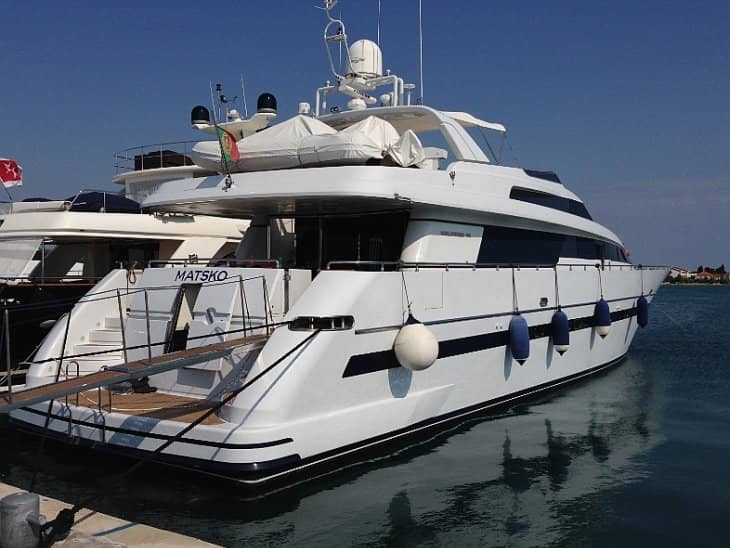
John Rushworth • 13 October 2015
Motor Yacht Matsko: Quiet, inexpensive energy
Introduction We were recently contacted by Josip Zdenković, a Director of SCHRACK TECHNIK Ltd in Croatia, who submitted a comprehensive technical article concerning the use of Victron Energy equipment on-board the vessel Matsko, shown in the headline image above. Here then in Josip’s s own words (translated from Croatian) is his detailed article about their project. Project assistance was provided by Josip Radin, also from SCHRACK TECHNIK, who was a co-worker on the project. Design brief: Quiet energy onboard with fuel savings The aim of Matsko’s investment company (Fuego Ltd.) was to have an AC power supply on-board, without using a generator or shore supply. The project was assisted by the fact that Fuego had all the necessary skills to wire the installation. Based on this information SCHRACK TECHNIK were able to develop a solution and supply the system components. All of the new essential components were manufactured and supplied by Victron Energy. Originally the vessel’s electricity was supplied by the on-board generators or shore supply. This resulted in the generators having to be used in quiet places in nature when anchored, as obviously no shore supply was available. This was particularly unwelcome at night when trying to enjoy a peaceful evening in some quiet hidden bay. Whilst no air conditioning was required throughout the evening and night, the generator was required to cover refrigerators and some lighting. Although electricity consumption was relatively small, there was always the irritation of the generator ‘muttering’ all night. Furthermore it is known that when a generator is operating in this way it is substantially under loaded, i.e. well below rated load, so unfortunately it is not running in a fuel efficient way. Generator fuel consumption was around 4 l/h at idle, i.e. with a light load, and 6 l/h at full load. The idea was therefore to completely shut down the generator in the evening and the morning and use ‘quiet energy’ to power the refrigerator and lighting. Then if the vessel were to sail during the day, the main engines would run, with both generators working which you can then load for any additional battery charging. This can achieve two objectives: when the generators are operating, they are working in the area of higher loads, so the better efficiency in terms of the number of litres of fuel with energy being produced more efficiently. Now any persons on-board can enjoy a peaceful sleep with ‘quiet energy’ being supplied for the night maintenance of the vessel, when at anchor. But it is also clear that by paying attention to the energy consumption at sea and when berthing in a marina connected to the shore supply, that instead of using the generators such an approach can reduce overall power consumption even further by using the silent low-cost shore energy to charge batteries, in order to be ready for sailing the following day. All of these goals can be achieved by adding a suitable battery bank to store energy which can then be used later. This desire for tranquillity on-board also decreases the overall operating costs of the system too. Motor Yacht Matsko Initial equipment state Figure 2 below is a representation of the pre-existing installation of the boat. The vessel installation is connected to shore via an isolation transformer, switch and main fuse. Loads on vessel are supplied from generators or from shore network. In the project the power system for safety critical ship systems is not shown at all because it must stay totally independent system. The red arrow marks the insertion point for the new part of the installation discussed in this article. Figure 2 – Simplified electrical installation of the vessel Technical solution for auxiliary power The new system has a 24 V DC battery bank , 880 Ah, C20 rated, using 8 interconnected batteries. See Figure 3. The cable connection from the battery to the busbars must all be the same length to balance the resistance of the individual parallel branches of the batteries. At the minus pole in the distribution box the measuring shunt of the BMV battery monitor is installed. The BMV battery monitor display is supplied from the minus terminals of the battery itself connected to the measuring shunt and from the positive pole of the battery bank, as shown in Figure 3. All plus poles of parallel branches of the battery bank are connected via ‘melting fuse’ on the plus busbar. The positive busbar is connected to the main battery switch. With this switch, all systems can be disconnected from the battery (except the battery monitor which s always powered on). The batteries are recharged via a three-phase Skylla charger; charging current is 100 A. The battery charger itself is concerned that the condition of the batteries can achieve optimum charging current for the current state of charge of the battery. From the battery through three autonomous inverters of the Phoenix type, a three-phase system is obtained. This inverter system can provide 3 x 3000 VA, 400V, 50 Hz rated. And the inverter system and battery charger have control inputs managing their work. The red arrows below show the direction of energy, from input to the battery bank via the charger and from the battery bank through the inverters to the output. Figure 3 – Auxiliary power system of the motor boat System Description: AC part Figure 4 below shows the wiring of the AC part, that is how the system is inserted into an AC installation. Switch S 1-0-2; the power switch, is used for the selection of the AC input of the vessel which can be powered by the shore supply or through the inverter system. The positions of switches S1-0-2 are explained in Figure 4. The charger is connected for normal loads in the vessel installation. The charger has its own input fuse so in such an installation it is not necessary to fit a new one. Inverters have overload protection built in, so in considering the point of connection and the existing protective/breaking devices in the vessel installation, there was no need for any additional special protection switches/circuit breakers. Figure 4 – Wiring AC part of the auxiliary power system for motor boat Matsko Figure 4a – Phoenix connections Control terminal for the realization of the three-phase system (see Figure 7) AC output: phases, zero and earth Battery connection Battery connection System Description: DC part Figures 5 and 6 below show the wiring and detail of the DC part of the battery bank. Figure 5 – Details of the battery bank and fuse boxes Figure 6 – Details of connecting the battery bank – connection inverters and chargers to the distribution boxes. Description of the system-control unit Figure 7 below shows the wiring for the control part. Inverters are connected to each other via a control connection in order to achieve a three-phase system (blue cable in Figure 7). Autonomous Phoenix inverters and charger do not operate simultaneously. When the inverter control input is in the closed condition, the inverters are supplying the voltage at the output. When this control input is in the open state, the inverters do not give the output voltage. Control input on the L1 Master unit controls the operation of all 3 inverters in this three phase system. When the charger Skylla control input is in the closed state, then the battery is not charging. When this control input is in the open position, the charger is charging. The charger can have all the time AC power at the power input, but only when the charger control input allows, the output voltage and therefore the power for charging batteries is released. Control switch 1-0-2, which is added on the charger housing, can choose whether inverters are working (then no charger), or the charger is working only (do not operate the inverters). Additional, inverter can only work if the relay contact from battery monitor is in the closed condition. Switched state of the relay is about the battery charge. If the battery is in good condition then inverters are operating normally. Should there be an excessive discharge of the battery, then the battery monitor relay contact is opened and that disables the inverters too. In this way, the battery bank is protected from deep discharge which enhances life expectancy. The charger is set to start charging always towards the maximum possible for the current state of charge of the battery. Inverters have one programmable relay output each that can be used for alarm/pre-alarm conditions like that the system will soon reach the voltage level when the battery master switch off inverter operation. This contact can be used for signalling required to switch the ship again to work through the generators before inverters system does battery self-protection shut down. Figure 7 – Management work chargers and inverters System Description – location of components Figure 8 shows the location of the main components. 1: Inverter first phase L1 2: 2nd inverter phase L2 3: 3rd inverter phase L3 (Master unit) 4: Battery charger Skylla 5: DC “-” Busbar box 6: DC “+” Busbar box 7: Power switch 1-0-2 8: Isolating transformer 9: Existing input box to control the power supply from the shore and checking phase sequence The batteries are located under the floor in the area where the equipment is located. The space is ventilated, as well as protected from dripping water. The red arrow shows how through a lack of care the water can spill onto the batteries. In this case the problem was tackled immediately so no damage was caused. It is clear than that the location choice of the batteries is extremely important. The same care must be carried out for proper inverter and charger ventilation. Figure 9. Detail installing batteries (choose location carefully to prevent overhead drips) Operating system Figure 10 below shows the location of the main components for management: power switch and control switch. Energy switch selects whether the shore network or inverters on board will supply the AC voltage to the board loads. Control switch is for selecting whether the inverters or chargers are in operation. Listed below are characteristic situations. The ship at sea under navigation: The energy switch is set to “2-network” or “0-opened.” Existing installation is ensuring that when on board generators are working, there cannot be shore mains voltage connection (which of course does not exist when navigating). The control switch must be 0 or 2, so that the battery charger operates and charges the battery with energy produced by generators. The ship at sea at rest: Energy switch in position 1- inverters in operation, control switch in position 1 inverters in operation. The whole ship’s installation draws its power from “quiet” sources, the boat is powered by batteries. The ship in the harbour with the presence of the shore supply: The energy switch is set to 2-shore supply, the control switch is set to 0 or 2, the battery charger operates and recharges the battery. Figure 10 .: Two main elements. The small black switches on the inverters and on the charger faceplates (red arrows shown in Figure 11) to ensure they work must be in the “on” position. It is not necessary to alter this whilst the ship is at sea or in the harbour, so they can be permanently in the on position. Figure 11 – Location of the switch to the exchangers, and the charger If the vessel is laid up over winter you need to turn off all devices. It is therefore recommended to disconnect the main battery switch on the “plus” side, and move the small black switches on the faceplates to off, as shown in Figure 11 above. Figure 12 -Location of battery switch on the “+” side In winter be sure that the main battery switch is turned off after the battery bank has been full charged first. This is important to maintain battery life. Also it is necessary at least once every two months to fully charge the batteries in order to provide the intended service life. Batteries require no maintenance other than once every two months providing a full charge! A full charge state shows the control voltage across the battery monitor. It is always on! After charging and without discharging any energy from the battery bank it must have 26V. It is especially important to emphasize that the maintenance of the battery contacts is very important too. If due to sea water, which is conductive, there is a short-circuiting of the battery the poles, that may cause irreversible destruction of the battery. Any corrosion on the terminals must be treated by regular maintenance, smearing with Vaseline grease. It is recommended to regularly check the condition of the overall battery bank, especially once every six months to look at all the electrical connections of the system and if necessary tighten them. Figure 13 below shows the complete ship’s auxiliary power system integration in the existing installation. In this diagram you can see clearly the differences in relation to Figure 2, which shows the initial state. Figure 13. Display systems integration auxiliary supply ship to ship existing installation. Conclusion We hope we have piqued your interest, and this simple yet complete depiction of this three-phase solution has demonstrated what can be achieved by “surgical” intervention to an existing installation. Of course, this system may not be fully applicable to your own case, but hopefully this may set you off on the path of emerging new ideas and thinking. In writing this article we also felt the need to explain what an isolating transformer is in order to ground the installation on-board, what an RCD does, what galvanic and electrolytic corrosion is – well that will need wait until another time where we may cover those topics separately and more comprehensively, as such factors are an important consideration too in an installation like this. Josip Zdenković Credits Josip Zdenković – article content, images and translation assistance to Victron Energy. Josip Radin – project assistance. Fuego Ltd. – Motor Yacht Matsko owners & investment company. SCHRACK TECHNIK Ltd of Croatia.
John Rushworth • 30 March 2015
Batteries: Lithium-ion vs AGM
In light of my last post concerning the use of the DC or Hybrid concept for electrical power , it occurred to me that the system could also have used monobloc AGM/Gel batteries or indeed a bank of long life 2 volt gel cells. In that case why was Lithium chosen? Hopefully this post may go some way to highlighting that decision process. Across all markets over recent years Lithium-ion batteries have been gaining in traction [sic]. To the uninitiated it is easy to dismiss Lithium-ion as an expensive alternative to VRLA (valve regulated lead acid) technologies such as AGM (absorbed glass mat), if simply looking at the amp-hour (Ah) rating. This was the initial mistake I made a few years back. Digging deeper it became clear to me that there is a lot more than Ah ratings to consider, when choosing the best batteries for your application. In the marine world (which is where I have the most experience) the choice these days and especially with higher loads – often simply comes down to Lithium-ion vs AGM. In the comparisons below whilst Gel batteries are shown, they do have a lower effective capacity at high discharge currents. They cost about the same as AGMs, assuming both types are monoblocs, as opposed to 2 V long life gel cells. Wet cell or flooded lead acid (FLA) batteries whilst referred to are not considered for the crux of this particular comparison, primarily due to maintenance and safety considerations in the marine environment. This of course may not apply to other markets. Useable energy and cost It is generally accepted that the most economic and practical depth of discharge (DOD) for an AGM battery is 50%. For Lithium-iron-phosphate (LiFePO4 or LFP) which is the safest of the mainstream Li-ion battery types, 80% DOD is used. How does this work out in the real world? Let’s take two Victron 24V battery examples and compare useable energy for a small yacht: 1 x Victron Lithium-ion 24 V 180 Ah The nominal voltage of the LFP cell is 3.3 V. This 26.4 V LFP battery consists of 8 cells connected in series with a 180 Ah rating. The available energy is 26.4 x 180 = 4. 75 kWh. Useable energy is 26.4 x 180 x 0.80 = 3.8 kWh . 2 x Victron AGM 12 V 220 Ah The nominal voltage of the lead-acid cell is 2.0 V/cell. Each 12 V monobloc battery consists of 6 cells connected in series with a 220 Ah rating. Connecting 2 x 12 V 220 Ah batteries in series to give 24V and 220 Ah, the available energy is 24.0 x 220 = 5.28 kWh. Useable energy is 24 x 220 x 0.50 = 2.64 kWh . This begs the question, what Ah rating of AGM batteries would be the equivalent of the 3.8 kWh useable energy of the Lithium-ion battery? To get 3.8 kWh of useable energy from an AGM battery it would need to be twice that size to start with due to the 50% DOD economy rule i.e. 3.8 x 2 = 7.6 kWh. At 24V that would mean 7,600/24 which gives us a battery rating of 316.66 Ah, which is moving closer to twice the rated capacity of the Lithium-ion 24 V 180 Ah. Note this does not take into account, the ageing of the batteries, temperature derating or the effect of higher loads. For AGM batteries, higher loads have a greater effect than on Lithium. See the section – Useable energy: effect on discharge capacity and voltage with differing loads, below. Based on all this it is reasonable to say that an AGM battery will need to be twice the Ah rating of a Lithium one. What about price? Using the Victron price list we see that a 12V 220 Ah AGM is € 470 ex VAT or 2.136 €/ Ah. For 316.66 Ah that is the equivalent of € 676.50 at 12V or € 1,353 at 24 V. The 24V 180 Ah Lithium is € 4,704 for the same amount of useable energy and is therefore 4,704/1,353 = 3.48 times more expensive ( or less if we consider the factor of 2 referred to above) when comparing Ah ratings. Based on this you might immediately conclude that Lithium is not cost effective, however useable energy compared to price is only part of the story. Weight Most Ah ratings of batteries regardless of type are specified at the 20 hour rate. This was fine in the days of light loads, but as the number of loads and the size of loads has increased over time, we also need to look at high short term loads, medium and longer term ones for differing types of equipment. This can mean a large battery pack. At the extremes we might have air conditioning running for 10 hours using 10 kW, compared to an LED light using 100 Watts in that time. Balancing these differing requirements and all the loads inbetween becomes key. With a large pack as shown below to achieve this, it becomes clear just how heavy Lead Acid can be compared to Lithium. 1360/336 = 4 times heavier . Useable energy: effect on discharge capacity and voltage with differing loads As stated earlier most batteries Ah rating are quoted at the 20 hr rate. In the image below for the lead acid battery, if that were a 100 Ah battery at the 20 hr rate, you can see that 0.05C means 100 x 0.05 = 5 Amps for 20 hours = 100 Ah available until the battery is totally flat. As we use only 50% of the battery we can see that the voltage will still be 24 V at 50% DOD for a 5 Amp load over 10 hours, and therefore we would have consumed 50 Ah. Increasing the current draw (as the graphs below show) can affect the useable energy available and battery voltage. This effective shrinkage in the rating is known as Peukert’s effect. With lead acid the higher the load, the more you need to increase the Ah capacity of your battery to help alleviate this. With Lithium however a load of even 10 times greater at 0.5C can still have a terminal voltage of 24V at 80% DOD/20% SOC , without going up on the Ah rating of the battery. This is what makes Lithium particularly suitable for high loads. Note: In the graphs below Discharge Capacity vs Terminal Voltage is shown. Usually you will see AGM graphs as Discharge Time vs Terminal Voltage. The reason we plot Discharge Capacity (instead of Discharge Time) is that Lithium has a higher and more stable terminal voltage than AGM, so plotting the curves with Discharge Capacity in mind gives a more accurate comparison of the chemistries, showing that Lithium increases useable energy at higher loads due to higher and more stable terminal voltages. Whilst you may consider this a grey area (in part too due to the varying internal resistance of batteries also) it is probably the only true way to compare the technologies. This is further demonstrated in the images below the graphs. Lithium – Discharge Capacity vs Terminal Voltage Lead Acid – Discharge Capacity vs Terminal Voltage Useable Energy (Lead Acid) Useable Energy (Lithium) Charge Efficiency Much that we have seen in the discharge process is also true in the converse process of charging. Don’t be put off by the large generator sizes shown below, as this blog merely shows a range of scenarios. Solutions are scalable in principal. First let’s compare charge efficiency of Lead Acid on the left to Lithium on the right, during the complete charge cycle. Charging the last 20% of a lead acid technology battery is always slow and inefficient when compared to Lithium. This is borne out in the fuel costs (or whatever charging source you use) in the images further down. Note the difference in charge times too. Note: Charge rates The recommended charge rate for large size AGM batteries is 0.2C i.e. 120A for a 600A battery consisting of paralleled 200Ah blocks. Higher charge rates will heat up the battery (temperature compensation, voltage sensing and good ventilation are absolutely needed in such a case to prevent thermal runaway), and due to internal resistance the absorption voltage will be reached when the battery is charged at only 60% or less, resulting in a longer absorption time needed to fully charge the battery. High rate charging will therefore not substantially reduce the charging time of a lead-acid technology battery. By comparison a 200Ah Lithium battery can be charged with up to 500A, however the recommended charge rate for maximum cycle life is 100A (0.5C) or less. Again this shows that in both discharge and charge that Lithium is superior. Battery choices, markets and cycle life Depending how you treat a battery you can reasonably expect the range of cycles below, subject to the DOD and the battery banks being properly sized for the loads. Operating temperature also comes into play. The hotter the battery the less time it will last. Battery capacity also reduces with ambient temperature. The baseline for variations due to temperature is 25 degrees Centigrade. Conclusions Clearly AGM batteries will need to be replaced more often than Lithium. It is worth bearing this in mind as this entails time, installation and transportation costs, which further negates the higher initial capital cost of Lithium as does the lower cost of recharging Lithium. No matter what battery choice you make there is also both a capital cost and technological risk at the outset. If you are in a position of having the capital for the higher upfront costs of Lithium, you might find that life is easier and that choice is a cost effective one over time. Much of this depends on the knowledge of the operator and how they treat a battery system. There is an old saying that batteries don’t die, they are killed. Good management practices are your insurance against early failure, regardless of the technology used. Lithium-ion vs AGM? The choice is yours. Personally I think the time is right to consider Lithium in the marine industry as a cost effective, reliable, high performance solution. Last week (it was only out of curiosity you understand) I went for a test drive in a Lithium-ion powered Tesla Model S – and as we know, no self-respecting electric vehicle manufacturer would still use lead acid based battery technologies today. Time for the marine industry to catch up? John Rushworth Credits Thanks to Reinout Vader and Johannes Boonstra for the images and technical advice in writing this blog. Further reading Whitepapers, inc Energy Unlimited by Reinout Vader: https://www.victronenergy.com/support-and-downloads/whitepapers Battery choices: https://www.victronenergy.com/batteries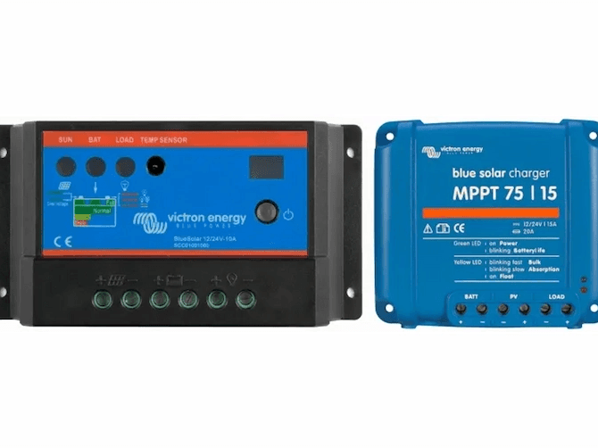
John Rushworth • 21 July 2014
Which solar charge controller: PWM or MPPT?
What follows is a summary of our white paper with the same title. For the full white paper, see: Which solar charge controller: PWM or MPPT? in the White papers section of our site. 1. What they do The PWM controller is in essence a switch that connects a solar array to a battery. The result is that the voltage of the array will be pulled down to near that of the battery. The MPPT controller is more sophisticated (and more expensive): it will adjust its input voltage to harvest the maximum power from the solar array and then transform this power to supply the varying voltage requirement, of the battery plus load. Thus, it essentially decouples the array and battery voltages so that there can be, for example, a 12 volt battery on one side of the MPPT charge controller and a large number of cells wired in series to produce 36 volts on the other. Example of a large number of cells wired in series to produce 36 volts Graphical representation of the DC to DC transformation as performed by an MPPT controller 2. The resultant twin strengths of an MPPT controller a) Maximum Power Point Tracking The MPPT controller will harvest more power from the solar array. The performance advantage is substantial (10% to 40%) when the solar cell temperature is low (below 45°C), or very high (above 75°C), or when irradiance is very low. At high temperature or low irradiance the output voltage of the array will drop dramatically. More cells must then be connected in series to make sure that the output voltage of the array exceeds battery voltage by a comfortable margin. b) Lower cabling cost and/or lower cabling losses Ohm’s law tells us that losses due to cable resistance are Pc (Watt) = Rc x I², where Rc is the resistance of the cable. What this formula shows is that for a given cable loss, cable cross sectional area can be reduced by a factor of four when doubling the array voltage. In the case of a given nominal power, more cells in series will increase the output voltage and reduce the output current of the array (P = V x I, thus, if P doesn’t change, then I must decrease when V increases). As array size increases, cable length will increase. The option to wire more panels in series and thereby decrease the cable cross sectional area with a resultant drop in cost, is a compelling reason to install an MPPT controller as soon as the array power exceeds a few hundred Watts (12 V battery), or several 100s of Watts (24 V or 48 V battery). 3. Conclusion PWM The PWM charge controller is a good low cost solution for small systems only, when solar cell temperature is moderate to high (between 45°C and 75°C). MPPT To fully exploit the potential of the MPPT controller, the array voltage should be substantially higher than the battery voltage. The MPPT controller is the solution of choice for higher power systems (because of the lowest overall system cost due to smaller cable cross sectional areas). The MPPT controller will also harvest substantially more power when the solar cell temperature is low (below 45°C), or very high (above 75°C), or when irradiance is very low. The summary above and the full white paper , has been written and compiled by Reinout Vader. John Rushworth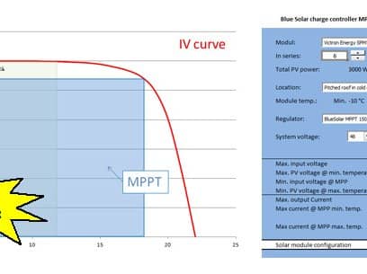
Bob Hopman • 28 March 2014
Matching solar modules to MPPT charge controllers
Life used to be so simple; in a 12V battery system you took a ‘12V’ solar module, watched carefully that the maximum PV current would not exceed the charge controller maximum current and the system would work. Unfortunately due to the fact, that with PWM controllers the PV module is not feeding the battery from its maximum power point (MPP), the system loses a lot of energy. In the following diagram you can see, the area of the MPP in blue (Vmpp * Impp) is up to 30% larger than the PWM area (Vbatt * ~Isc) within the IV curve. So, with the advent of the newer Victron Energy Blue Solar MPPTs, things changed for the better when compared to PWM solar charge controllers. If a specific yield is the goal, the 30% higher efficiency of the MPPT will reduce system costs, because the same energy can now be produced with a smaller PV generator. If the size of the solar module was already fixed, the yield is now higher in the same system when using an MPPT. In both cases the user is a winner! Sizing the system can be done electrically to see if the system is allowed and will not destroy any components, when looking at the yield to see how much energy it will produce. For now I will look at the first part, to find out what is possible on the electrical side. By adding a DC/DC converter in the Blue Solar MPPT controller, the system also becomes more flexible when we look at the input voltage of the controller. The challenge now, is to match the PV modules to the controller, because we are not concentrating on only ‘12V’ or ‘24V’ modules anymore. Basically any module can now be used if it is within the input voltage range of the charge controller. In fact we can now put modules in series as well as parallel, which will also increase the input power and flexibility. Thanks to the output power or current limiter, the output power will never exceed the maximum of the controller. This Blue Solar MPPT feature is unique and makes the charge controller even more interesting! You can now for example add the same type of modules in parallel later without the need to change the MPPT charge controller. This reduces costs to a minimum, whilst still increasing the yield! Also, I took the values for all our Blue Solar MPPT charge controllers and Blue Solar modules and combined them into a Spreadsheet. Now sizing a Blue Solar MPPT charge controller is easy! Download: VE-MPPT-Calc.xlsx (744KB) – This configuration spreadsheet is compatible with MS Excel. Now for the technical explanation, for those who would like to know some more details: Exceeding the input voltage range will (as it did with the PWM controllers) damage the controller permanently. Of course we will also need to take a look at the minimum voltage, where the Blue Solar MPPT controller will start working. If you take a SPM50-12, the Open Circuit Voltage (Voc) is 22.2V and the maximum power voltage (Vmpp) is 18V at Standard Test Conditions (STC) which means 1.000W/m² irradiation, 25°C cell temperature and an Airmass of 1.5. If the cell temperature is higher or less than 25°C, this voltage reduces or increases due to the temperature coefficient, in this case -0.34%/°C (see Blue Solar module datasheet). So if you take 3 modules SPM50-12 on a Blue Solar MPPT 150/70 in a 48V system on cold days say, -10°C (only looking at the voltage), you can start up charging: The startup voltage is 48V + 7V (see MPPT 150/70 datasheet) = 55V The modules will produce 3 * ( 22.2V + (-0.34% of 22.2V * -35°C temperature difference)) = 74.5V 74.5V is higher than 55V -> that’s perfect Also running in the MPP the system would work: The running voltage is 48V + 2V (see MPPT 150/70 datasheet) = 50V The modules will produce 3 * ( 18V + (-0.34% of 22.2V * -35°C temperature difference)) = 61.9V 61.9V is higher than 50V -> that’s perfect Doing the same thing, when the modules get warm during the day, in this case 70°C you can see what happens: The startup voltage is still 48V + 7V (see MPPT 150/70 datasheet) = 55V The modules will produce 3 * ( 22.2V + (-0.34% of 22.2V * 45°C temperature difference)) = 56.4V 56.4V is higher than 55V -> that would work But now in the MPP the module voltage is lower than the minimum: The running voltage is 48V + 2V (see MPPT 150/70 datasheet) = 50V The modules will produce 3 * ( 18V + (-0.34% of 22.2V * 45°C temperature difference)) = 43.8V 43.8V is lower than 50V -> this is not enough! The high DC/DC conversion efficiency (97.5% at 48V) will result in following output maximum charging current (@ -10°C) of 61.9V Vmpp* 2.74A Impp / 48V Battery voltage * 0.975 Efficiency = 3.45A This is far below the maximum of 70A, so it will be all used to charge the battery. Increasing the number of modules per string to 6 in series and making 10 strings in parallel gives the following result at -10°C: The Voc will remain under the maximum of 150V at -10°C Now at high temperatures such as a 70°C cell temperature the system will work just fine! Taking this example in the Spreadsheet you can now increase the number of strings in parallel and you will see, if starting at 11 strings, that the controller will start to reduce power. The big advantage in doing this is that you will now produce the maximum controller output at a lower irradiation. As module prices decrease, this is an effective option. Please note, that you can use ‘preconfigured’ minimum and maximum temperatures. I’ve also given some installation examples, at the bottom of the spreadsheet, with their anticipated module temperatures for various types of installations. Oversizing a PV array Oversizing a PV array means installing more peak power (Wp) than the maximum charge power of the chosen MPPT charge controller. A common reason to oversize is to cater for winter time when the sun is not as powerful. The MPPT solar sizing calculator will allow for a 130% PV array oversizing when recommending a charge controller. The design logic is that panels RARELY spend much time at their peak rated output capacity, only maybe an hour in the middle of a sunny day. The rest of the time they are derated below their spec maximum, and less than the maximum capacity of the charge controller. Some installers don’t like to do this however, and will override it so that the panel output is never constrained. The best choice will depend on the installation, and may take into account a limited roof area, or limited solar window (due to shading). Another reason to oversize panel to charge controller capacity is that PV panel output degrades over time, as they get soiled, dirty, PID, etc. Generally total energy harvested from a 130% panel oversizing results in less than 1% annual energy loss. Limits to Oversizing a PV array How to determine by how much you can oversize a PV array? This can be done with help from the spreadsheet tool . Here though is the manual explanation of how it is done. There are two limits, when determining the maximum array size that can be connected to an MPPT: The Maximum PV open circuit voltage (Voc at STC) The Maximum PV short circuit current (Isc at STC) Both values are specified in the datasheets of all our MPPT Solar Charge Controllers . Those two ratings of the PV array must not exceed these MPPT limits. Note that these two maximum ratings must not be multiplied to determine the maximum installable peak power. Instead, each of them needs to checked by itself: Determining the maximum PV open circuit voltage First look at the datasheets of the solar panels to see what their maximum open circuit voltage is. Then multiply that by the number of panels that are in series in the array. The result of the multiplication must not be higher than the Maximum PV open circuit voltage as listed on the MPPT Datasheet. Make sure to take into account the coldest expected temperature. The colder it is, the higher the open circuit voltage on a PV array will be. Determining the maximum PV short circuit current Get the maximum PV short circuit current from the PV Panel datasheet. Multiply by the number of panels in parallel in the array. Having more panels in series does not change the number. The result of the calculation may not exceed the Max PV short circuit current as specified in the MPPT Datasheet. Good luck and enjoy sizing the BlueSolar MPPT Charge Controller! Kind regards, Bob Hopman – Victron EnergyNeed advice? Our highly trained dealers are happy to help with questions, small or large.
Find a dealer near you
Check our support resources or contact your original dealer for dedicated support, repairs or warranty requests.
Support
Read more about our industry-leading 5-year standard warranty and global repair service.
Warranty


©Victron Energy 2026
